Switching power circuit

A technology of switching power supply circuits and switching tubes, which is applied to electrical components, adjusting electrical variables, instruments, etc., can solve the problems of no change in driving switching tube voltage, large output stage area, and increased chip cost, so as to reduce power consumption, The effect of small chip area and improved efficiency

Inactive Publication Date: 2012-12-05
UNIV OF ELECTRONIC SCI & TECH OF CHINA
View PDF4 Cites 19 Cited by
  • Summary
  • Abstract
  • Description
  • Claims
  • Application Information

AI Technical Summary

Problems solved by technology

However, this output stage separation scheme increases the cost of the chip due to the large area of ​​the output stage used.
[0006] The scheme of the switching power supply circuit of the second PFM control mode is as follows: figure 2 As shown, in this mode, as the load becomes lighter, the frequency decreases and the response speed is fast, but the output ripple is large, and the voltage of the driving switch tube does not change at light load, which limits the further reduction of power consumption
However, this solution also has the same problem that the voltage of the driving switch tube does not change, which limits the further reduction of power consumption; at the same time, when the load changes suddenly and the mode switches, a large ripple will be generated.

Method used


Image

  • Switching power circuit
  • Switching power circuit
  • Switching power circuit

Examples


Embodiment Construction

[0019] The present invention will be further described below in conjunction with the accompanying drawings and specific embodiments.

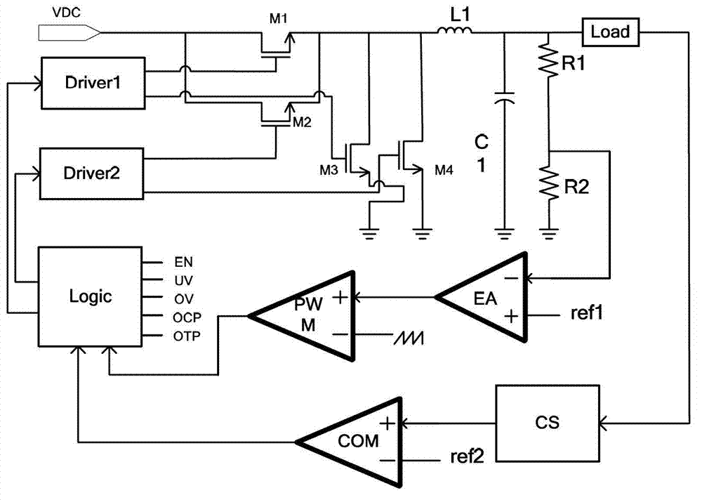
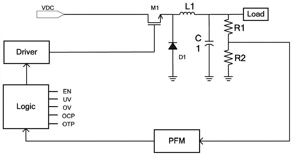
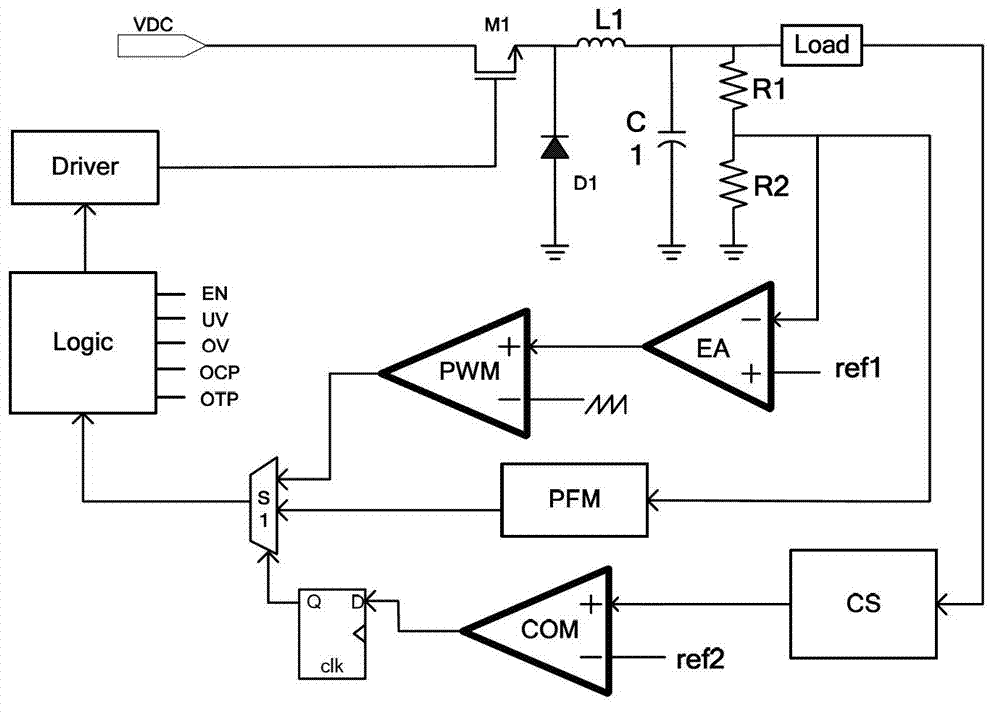
[0020] Figure 4 It is shown that the switching power supply circuit of this example includes the first voltage dividing resistor R1, the second voltage dividing resistor R2, the inductance element L, the freewheeling diode D1, the load unit Load, the load current detection unit CS, the comparator COM, and the D latch device, analog-to-digital converter ADC, digital-to-analog converter DAC, PWM working mode gate drive voltage generation unit VPWM, first amplifier EA, PWM comparator, PFM control unit, two-to-one selector S1, S2, digital logic unit Logic , Gate drive unit Driver.

[0021] The specific connection relationship is: one end of the first voltage dividing resistor R1 is connected to the first end of the inductance element L and serves as the output end of the switching power supply circuit, and the other end is grounded through the se...


PUM


Abstract

The invention discloses a switching power circuit, which comprises a switching tube, a first resistive divider, a second resistive divider, an inductive component, a freewheel diode, a load unit, a load current detection unit, a comparator, a D latch, an analogue-to-digital converter, a digital-to-analogue converter, a pulse width modulation (PWM) operating mode gate driving voltage generation unit, a first amplifier, a PWM comparator, a pulse frequency modulation (PFM) control unit, a first either-or selector, a second either-or selector, a digital logic unit and a gate driving unit. When a PFM control mode is adopted, the voltage of the switching tube is regulated according to a load to reduce power consumption in a light load condition and improve energy transmission efficiency; and in addition, in the light load condition, the gate driving voltage and switching duty cycle of the switching tube are reduced, so that the power consumption is simultaneously reduced, and the shortcoming that output power is regulated only dependent on the duty cycle of the switching tube to narrow the variation range of the duty cycle and further retard the sudden change of the load and cause large output ripples during mode switching is overcome.

Description

technical field [0001] The invention belongs to the technical field of power supplies, and in particular relates to the design of a switching power supply circuit. Background technique [0002] Switching power supply has the advantages of small size, light weight, high efficiency, low heat generation, stable performance, etc., and is widely used in various terminal equipment and communication equipment mainly based on electronic computers. [0003] There are three common working modes of switching power supply: PWM (Pulse Width Modulation) mode, PFM (Pulse Frequency Modulation) mode and PWM / PFM mixed mode. PWM mode has low noise, high efficiency at full load and can work in continuous conduction mode, but due to the fixed frequency, the switching loss of its control circuit is generally large, and the efficiency decreases at light load. The frequency of PFM mode decreases as the load becomes lighter, so the efficiency is improved; and without the influence of the first ampl...

Claims


Application Information

Patent Timeline
IPC IPC(8): H02M3/156
Inventor 方健陶垠波吴杰潘福跃杨毓俊唐莉芳黎俐臧凯旋
Owner UNIV OF ELECTRONIC SCI & TECH OF CHINA
Why Eureka
Try Eureka