Engine thermal management system

A thermal management system and engine technology, applied in engine components, machines/engines, engine cooling, etc., can solve problems affecting engine work efficiency, backward cooling methods, low engine temperature, etc., to reduce pollutant emissions and maximize efficiency. The best effect of reducing fuel consumption

Active Publication Date: 2012-12-12
CAMALUOYANGELECTROMECHANIC
View PDF6 Cites 13 Cited by
  • Summary
  • Abstract
  • Description
  • Claims
  • Application Information

AI Technical Summary

Problems solved by technology

[0002] The conventional engine cooling water-cooling system has poor environmental adaptability. It is easy to cause high temperature of the engine in summer and low temperature of the engine in winter, which affects the working efficiency of the engine.
The cooling method of the vehicle intercooler is relatively backward. Most of them drive the belt from the engine output shaft, and the belt drives a large cooling fan through the belt on the intermediate shaft to cool down the radiator. Therefore, as long as the engine is running, the fan will run, and the fan operation is almost independent Factor control, in many states (waiting at a red light on the road, vehicles entering a station, parking), resulting in a large waste of energy

Method used


Image

  • Engine thermal management system
  • Engine thermal management system
  • Engine thermal management system

Examples


Embodiment 1

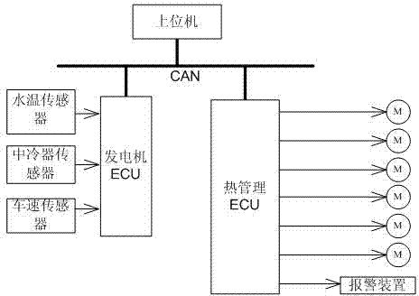
[0016] like figure 1 , for vehicles with CAN network, the engine thermal management system is built on the basis of the original vehicle electrical control system. The original vehicle electrical control system includes a CAN bus. The CAN bus is connected with a host computer and an engine ECU, and the engine ECU is connected with a vehicle speed sensor (the above belongs to the prior art and will not be described in detail). On this basis, install the engine water temperature sensor and the intercooler temperature sensor at the corresponding positions of the engine and the intercooler in the car. These two sensors are also connected to the engine ECU, and the engine ECU performs A / D conversion on the output signals of the two sensors. , the converted data is sent to the CAN bus, and is taken by the thermal management ECU connected to the bus. After processing and analysis, it drives a corresponding group of cooling fans. In this embodiment, the group of cooling fans includes ...

Embodiment 2

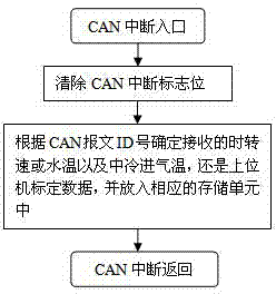
[0021] like Figure 5 As shown, this implementation is suitable for vehicles without CAN network. At this time, the engine water temperature sensor and the intercooler temperature sensor are connected to the thermal management ECU, so the thermal management ECU should have a corresponding AD interface, that is, an analog signal acquisition port. Image 6 It is a process of AD acquisition by means of timing interruption. In Embodiment 1, these AD interfaces can also be reserved for the thermal management ECU for backup.

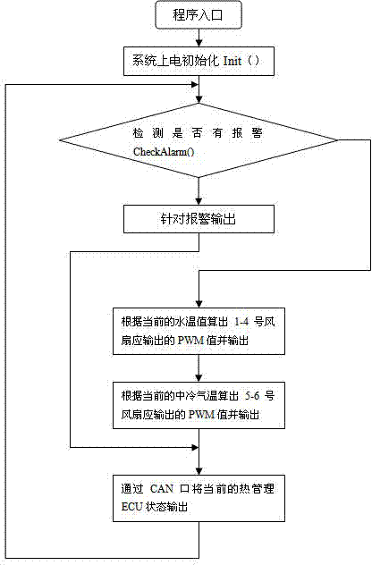
[0022] In this embodiment, the thermal management ECU directly controls the fan according to the collected information, and the specific process will not be repeated here.


PUM


Abstract

The invention relates to an engine thermal management system. The system comprises an upper computer and an engine electronic control unit (ECU), the upper computer is connected with an in-vehicle controller area network (CAN) bus, the engine ECU is connected with an engine water temperature sensor, an intercooler sensor and a vehicle speed sensor in a sampling mode, the engine thermal management system further comprises a thermal management ECU which is connected with the in-vehicle CAN bus, the thermal management ECU outputs a pulse width modulation (PWM) signal to be connected with a group of cooling fans in a driving mode, the group of cooling fans is used for cooling engine water temperature and an intercooler, and the thermal management ECU is further connected with an alarm device in a drive control mode. According to the engine thermal management system, the heat-dissipating mode of the vehicle intercooler is changed from mechanical power type to electronic type, the operation of the cooling fans can be automatically controlled according to the temperature information of the engine, and the engine is maintained in the optimum working temperature.

Description

technical field [0001] The invention relates to engine thermal management equipment, which belongs to the technical field of engine thermal management. Background technique [0002] The conventional engine cooling water-cooling system has poor environmental adaptability. It is easy to cause high temperature of the engine in summer and low temperature of the engine in winter, which affects the working efficiency of the engine. The cooling method of the vehicle intercooler is relatively backward. Most of them drive the belt from the engine output shaft, and the belt drives a large cooling fan through the belt on the intermediate shaft to cool the radiator. Therefore, as long as the engine is running, the fan will run, and the fan operation is almost independent of other Factor control, in many states (waiting at a red light on the road, vehicle entering a station, parking) causes a large waste of energy. Contents of the invention [0003] The purpose of the present inventio...

Claims


Application Information

Patent Timeline
Patent Type & Authority Applications(China)
IPC IPC(8): F01P7/08F01P7/04
Inventor 吕水莲刘仁杰王凤魁王中先张炜黄国宁张学申马洲李奇峰郭玉峰由小俊
Owner CAMALUOYANGELECTROMECHANIC
Why Eureka
Try Eureka