Air purifier for membrane separation
An air purification device and membrane separation technology, applied in separation methods, climate change adaptation, dispersed particle separation, etc., can solve the problems of single performance and high cost of air purifiers, achieve good social and economic benefits, low energy consumption, The effect of the simple structure of the device
- Summary
- Abstract
- Description
- Claims
- Application Information
AI Technical Summary
Problems solved by technology
Method used
Image
Examples
Embodiment 1
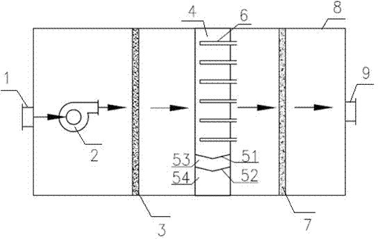
[0037] Such as figure 1 The shown air purification device includes a housing 8, an air inlet 1 and an air outlet 9 arranged at both ends of the housing 8, and the housing 8 includes a blower fan 2, a pre-filter 3, and a separation membrane assembly arranged in sequence. The clean room 4 and activated carbon net 7.
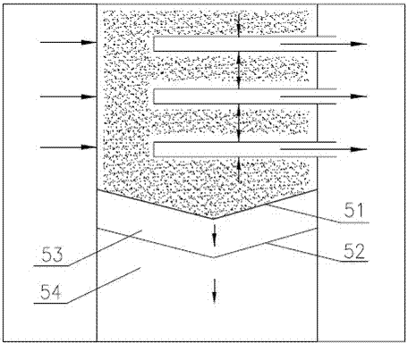
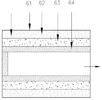
[0038] Such as figure 2 As shown, the separation membrane module includes three tubular membranes (namely, separation membrane 6) made of ceramic materials. The diameter of the inner channel of the tubular membrane is 8mm, the pore diameter of the outer membrane is 0.05μm, the porous support layer and the porous embedded The layer pore size is 5 μm. Among them, such as image 3 As shown, the separation membrane 6 includes a four-layer structure, which is an outer membrane layer 61 , a porous support layer 62 , a catalyst particle layer 63 , and a porous inner layer 64 . The catalyst particle layer 63 is used for decomposing indoor volatile organic compounds such...
Embodiment 2
[0042] Compared with Example 1, the difference is only that, as figure 2 As shown, in this embodiment, the bottom of the clean room 4 is also provided with a dust collection assembly, which includes a double-layer mechanical flap valve composed of two V-shaped mechanical flap valves 51, 52 and a double-layer mechanical flap valve. The upper and lower dust collection chambers 53, 54 formed by the plate valve and the side wall of the clean room. Mechanical flap valves are used between the clean room and the upper and lower dust collection rooms to collect particles. The dust retained by the separation membrane module can be discharged into the upper dust collection chamber 53 and the lower dust collection chamber 54 for timely cleaning.
Embodiment 3
[0044] Compared with embodiment 1, the difference is only in: as Figure 4 As shown, the separation membrane in this embodiment is in a honeycomb configuration, and the separation membrane assembly includes two honeycomb configuration membranes made of ceramic materials. The diameters of the dusty gas channel and the purified gas channel are both 8mm, and the thickness of the outer membrane layer 61 is 0.01 μm, pore diameter 0.1 μm, porous support layer 62 thickness 1.5 mm, pore diameter 4 μm, catalyst particle layer 63 thickness 1 mm, porous inner layer 64 thickness 1 mm, pore diameter 4 μm. In addition, in this embodiment, the pre-filter 3 is a gelled cotton net with a pore size of 1 mm, and the activated carbon net 7 is filled with columnar activated carbon.
PUM
| Property | Measurement | Unit |
|---|---|---|
| diameter | aaaaa | aaaaa |
| pore size | aaaaa | aaaaa |
| pore size | aaaaa | aaaaa |
Abstract
Description
Claims
Application Information
 - R&D
- Intellectual Property
- Life Sciences
- Materials
- Tech Scout
- Unparalleled Data Quality
- Higher Quality Content
- 60% Fewer Hallucinations
Browse by: Latest US Patents, China's latest patents, Technical Efficacy Thesaurus, Application Domain, Technology Topic, Popular Technical Reports.
© 2025 PatSnap. All rights reserved.Legal|Privacy policy|Modern Slavery Act Transparency Statement|Sitemap|About US| Contact US: help@patsnap.com


