PSD (Position Sensitive Detector)-based industrial robot self-calibration method and device

An industrial robot and robot technology, applied in the direction of measuring devices, optical devices, instruments, etc., can solve the problem that it is difficult to obtain high measurement accuracy in terms of field of view and resolution, cannot perform self-calibration of robot space pose, and data acquisition is time-consuming and laborious, etc. problem, to achieve the effect of high measurement accuracy, simple installation and operation, and simple structure

Inactive Publication Date: 2012-12-19
NORTH CHINA ELECTRIC POWER UNIV (BAODING)
View PDF7 Cites 55 Cited by
  • Summary
  • Abstract
  • Description
  • Claims
  • Application Information

AI Technical Summary

Problems solved by technology

The above-mentioned measuring instruments are quite different in terms of accuracy, cost, and ease of use, but they all have the disadvantages of requiring professional technicians to operate these instruments, time-consuming data collection, difficulty in automation, high cost, and cumbersome measurement methods;
[0005] The second method is to add external redundant sensors, and realize the self-calibration of robot kinematics parameters through the information provided by the sensors. The reason is that the camera itself needs to be calibrated, and it is difficult to obtain high measurement accuracy due to the contradiction between field of view and resolution
[0006] The third method is to solve the kinematic parameters by imposing physical constraints with known positions or known shapes in the robot workspace, using the end of the robot to contact these constraints, forming a closed kinematics chain and establishing constraint equations. For example, the Chinese invention patent number is CN101968341A discloses a zero-position self-calibration method and device for an industrial robot. Firstly, a PSD device is arbitrarily placed in the reachable workspace of the robot, and then only depends on a beam of laser passing through the end of the robot to automatically position and project on the robot at different positions. The center point of the PSD can realize the calibration task of the robot, but this method can only perform self-calibration of the zero position deviation, and cannot perform self-calibration of the robot space pose, and when performing the self-calibration of the zero position deviation, the end of the robot or a laser is required The spot is projected to the center of the PSD from at least 7 different orientations, so the calibration process is complicated

Method used


Image

  • PSD (Position Sensitive Detector)-based industrial robot self-calibration method and device
  • PSD (Position Sensitive Detector)-based industrial robot self-calibration method and device
  • PSD (Position Sensitive Detector)-based industrial robot self-calibration method and device

Examples


Embodiment Construction

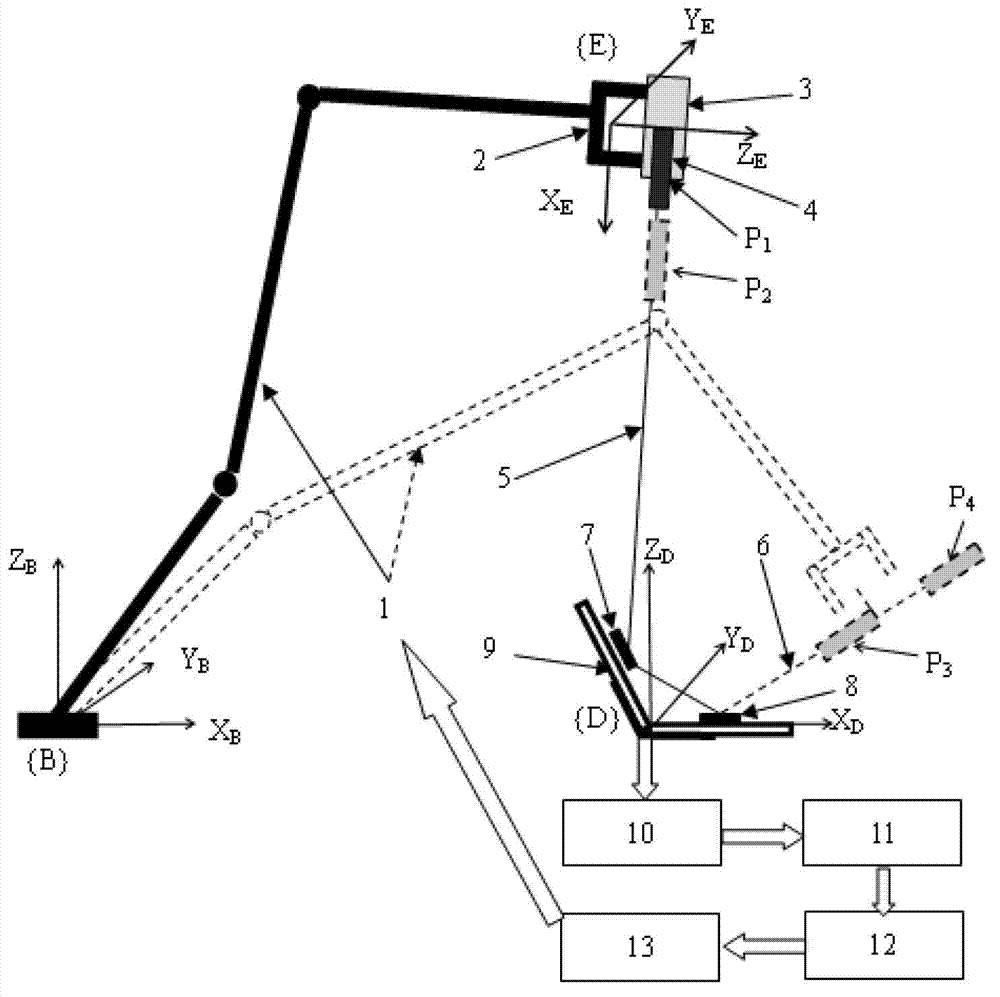
[0046] Such as figure 1 Shown is the structural representation of the self-calibration device for an industrial robot based on PSD of the present invention, which includes: a robot 1; a laser 4 installed at the end 2 of the robot; a V-shaped clamp 9 arranged in the accessible workspace of the robot 1; respectively Two position-sensitive device PSDs installed on the two plates of the V-shaped fixture 9, i.e. the first PSD7 and the second PSD8, wherein, when the robot is in different positions, the laser beam emitted by the laser is projected on the first PSD or the second PSD on, so as to form the projection spot and the reflection beam, and the reflection beam is projected onto the second PSD or the first PSD to form the reflection spot; the robot closed-loop control unit connected with the first PSD7 and the second PSD8 respectively, which will project the spot and reflection The light spots are respectively positioned at the center point positions of the first PSD7 or the se...


PUM


Abstract

The invention discloses a PSD (Position Sensitive Detector)-based industrial robot self-calibration device, wherein two PSDs are arranged on two plates of a V-shaped clamp respectively; the V-shaped clamp is placed in an achievable range of a robot; when the robot is at different positions, a projection light spot and a reflection light spot of a laser beam emitted by a laser which is fixedly arranged at the tail end of the robot are positioned at positions of central points of the two PSDs respectively; and self-calibration of zero offset of the robot and self-calibration of a spatial posture are performed through two virtual constraint lines. The self-calibration device has a simple structure and is easy to mount and operate and high in positioning accuracy, and the self-calibration of the spatial posture and the zero offset of the robot can be simultaneously realized; and the invention also provides a PSD-based industrial robot self-calibration method.

Description

technical field [0001] The invention belongs to the technical field of calibration of industrial robots, and in particular relates to a self-calibration method and device for zero position deviation and space pose of a 6-degree-of-freedom industrial robot based on PSD and laser virtual constraint lines. technical background [0002] With the continuous expansion of the application range of industrial robots in industrial production and the complexity of the tasks completed, the requirements for the pose accuracy of industrial robots are also getting higher and higher. At present, most commercialized robots have very high repetition accuracy, which can reach the order of 0.1mm, but their positioning accuracy is very poor, which can only reach the order of cm. Such positioning accuracy is far from meeting the requirements of modern industrial development. There are many reasons for the low positioning accuracy of industrial robots, such as parameter deviations of robot kinemat...

Claims


Application Information

Patent Timeline
Patent Type & Authority Applications(China)
IPC IPC(8): B25J9/10B25J9/16G01B11/26
Inventor 杜必强席宁
Owner NORTH CHINA ELECTRIC POWER UNIV (BAODING)
Why Eureka
Try Eureka