
Laser-single mode fiber remote signaling signal sampling device

A single-mode optical fiber, remote signaling signal technology, applied in the direction of telemetry/remote control selection device, selection device, optical fiber transmission, etc., can solve the problems of high power consumption, malfunction of protection device, electromagnetic interference, etc. Reliable, simple structure effect

Active Publication Date: 2014-05-14
DALIAN POWER SUPPLY COMPANY STATE GRID LIAONING ELECTRIC POWER +1
View PDF6 Cites 0 Cited by
  • Summary
  • Abstract
  • Description
  • Claims
  • Application Information

AI Technical Summary

Problems solved by technology

[0002] The remote control and remote signaling signal acquisition device of the existing power grid mainly relies on the on-off of the DC circuit to reflect the opening and closing status of power equipment such as circuit breakers and knife switches. It mainly has the following deficiencies: First, the DC grounding problem. The DC floating battery power supply of the substation is used, that is, the DC bus voltage of +110V and -110V is directly used as the remote signaling power supply, and +110V is the common terminal of the remote signaling circuit. , cable wiring construction error, etc., a DC grounding fault will occur, resulting in a malfunction of the protection device, resulting in a large-scale power outage
Second, the SOE resolution of the signal at the same point is low. Since a large number of jitter signals will be generated during the operation of the auxiliary contact of the traditional contact signal, the remote signal acquisition circuit must adopt jitter filtering processing on hardware and software, which makes it difficult to realize the same point. 2ms SOE resolution requirement
The third is that the power consumption is large, and there is an electromagnetic interference problem. A 32-channel DC remote signaling acquisition board usually consumes about 10W, and the full load power will be higher. Because it is close to high-voltage equipment, it is vulnerable to electromagnetic interference and sends out wrong signals.

Method used


Image

  • Laser-single mode fiber remote signaling signal sampling device
  • Laser-single mode fiber remote signaling signal sampling device

Examples


Embodiment Construction

[0011] The present invention will be further described below in conjunction with accompanying drawing:

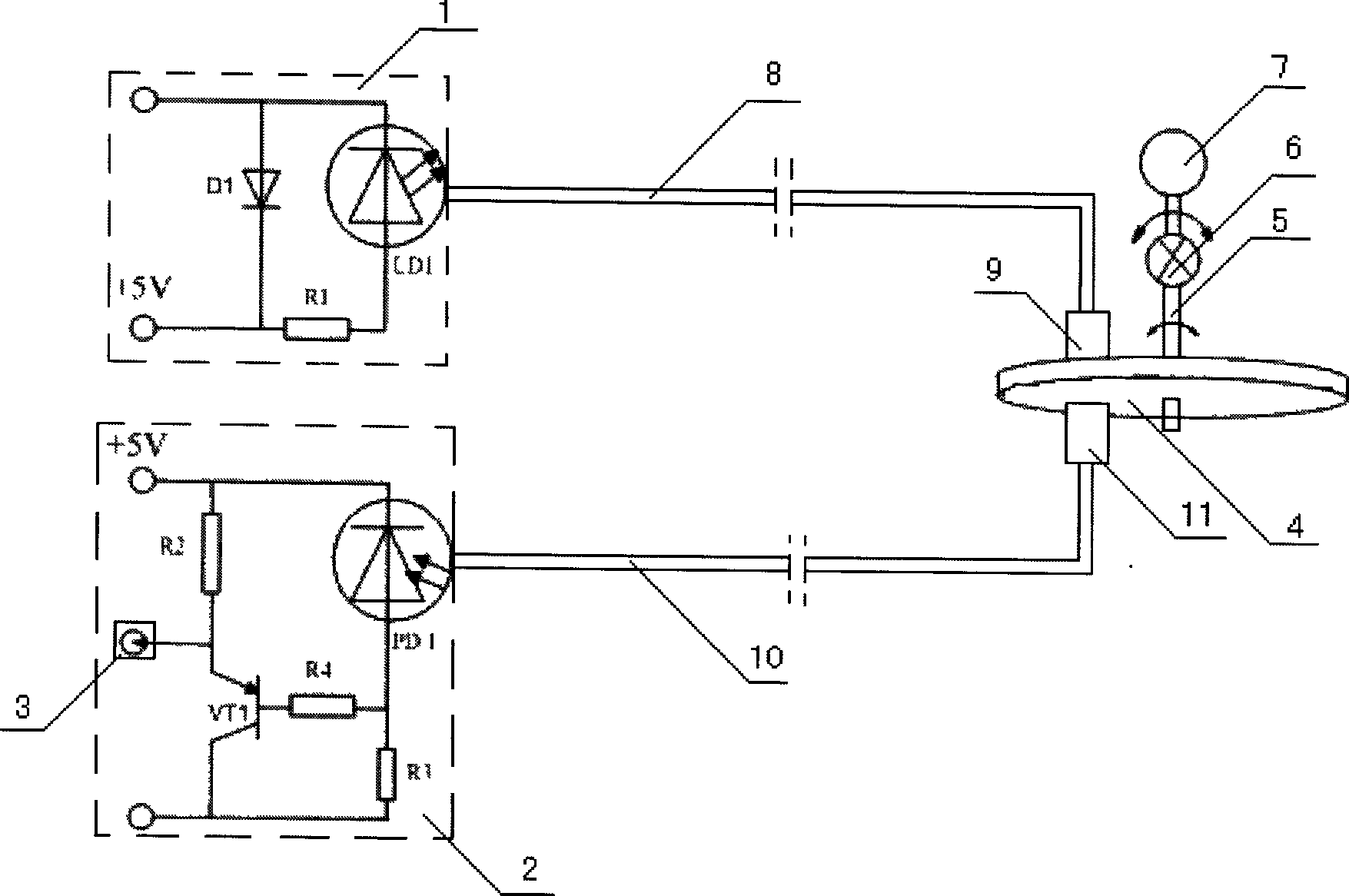
[0012] Such as figure 1 As shown, the laser transmission circuit 1 of the laser and single-mode optical fiber remote signaling signal acquisition device is connected to one end of the single-mode optical fiber 8, and the pigtail adapter 9 at the other end of the single-mode optical fiber is correspondingly installed in the optical through hole on the side of the optical signal circuit breaker 4. Above, the laser signal receiving circuit 2 is connected to one end of the single-mode optical fiber 10, and the pigtail adapter 11 at the other end of the single-mode optical fiber is correspondingly installed on the optical through hole on the other side of the optical signal switch.

[0013] The laser sending circuit is composed of power supply, resistor R1, diode D1 and laser diode LD1. The power supply is a 5V DC power supply, and the resistor R1 is used to meet the requiremen...


PUM


Abstract

A laser and single-mode optical fibre telesignalization signal acquisition device, including a laser sending circuit (1), a single-mode optical fibre (8), an optical signal switch (4) and a laser signal receiving circuit (2). The laser sending circuit (1) is connected to one end of the single-mode optical fibre (8), and a pigtail adaptor (9) at the other end of the single-mode optical fibre (8) is correspondingly installed on an optical through-via at one side of the optical signal switch (4). The laser signal receiving circuit (2) is connected to one end of a single-mode optical fibre (10), and a pigtail adaptor (11) at the other end of the single-mode optical fibre (10) is correspondingly installed on an optical through-via at the other side of the optical signal switch (4). The device feeds back the operating status of the monitored apparatus using the ON / OFF of the optical signal circuit and transmits the telesignalization information to the monitoring apparatus, with a simple structure, reliable performance, low power consumption, and resistance to electromagnetic interference.

Description

technical field [0001] The invention relates to a remote monitoring device for grid information, in particular to a laser and single-mode optical fiber remote signaling signal acquisition device. Background technique [0002] The remote control and remote signaling signal acquisition device of the existing power grid mainly relies on the on-off of the DC circuit to reflect the opening and closing status of power equipment such as circuit breakers and knife switches. It mainly has the following deficiencies: First, the DC grounding problem. The DC floating battery power supply of the substation is used, that is, the DC bus voltage of +110V and -110V is directly used as the remote signaling power supply, and +110V is the common terminal of the remote signaling circuit. , Cable wiring construction accidents, etc., a DC grounding fault will occur, resulting in a malfunction of the protection device and causing a large-scale power outage. Second, the SOE resolution of the signal...

Claims


Application Information

Patent Timeline
Patent Type & Authority Patents(China)
IPC IPC(8): H02J13/00G08C23/06
CPCH04Q9/00H04B10/25H04Q2209/30
Inventor 石文江阴晓光
Owner DALIAN POWER SUPPLY COMPANY STATE GRID LIAONING ELECTRIC POWER
Learn More