Digital pulse width modulator circuit

A width modulation, digital pulse technology, applied in the field of electronics, can solve the problems of linearity limitation, delay calibration difficulty, not considering the mismatch of each delay unit, etc., to achieve the effect of low power consumption

Active Publication Date: 2012-12-19
UNIV OF ELECTRONIC SCI & TECH OF CHINA
View PDF7 Cites 47 Cited by
  • Summary
  • Abstract
  • Description
  • Claims
  • Application Information

AI Technical Summary

Problems solved by technology

The analog unit can continuously adjust the delay, while the digital unit can only be adjusted discretely, which will bring difficulties to the delay calibration of each unit during design, considering the delay caused by process, voltage and temperature deviation The delay of the unit changes, and the linearity is greatly limited
At present, the common control method i

Method used


Image

  • Digital pulse width modulator circuit
  • Digital pulse width modulator circuit
  • Digital pulse width modulator circuit

Examples


Embodiment 1

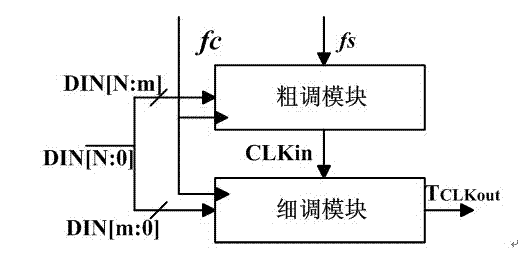
[0037] As a preferred embodiment of the present invention, the present invention discloses a digital pulse width modulator circuit, including a coarse adjustment module and a fine adjustment module, and also includes an RS flip-flop, and the coarse adjustment module includes a 5-bit counter and 5-bit comparators, the fine-tuning module includes a delay chain, "5 select 32" multiplexers and an all-digital logic control module; in the rough-tuning module, the input of the 5-bit counter is a standard clock signal, and the output Connect to the input terminal A of the comparator, and the input terminal B of the comparator is connected to the high 5-bit DIN of the control code DIN, the output signal of the coarse adjustment module is CNT_OUT, and the first digital controllable delay unit in the fine adjustment module The input port IN[0] is connected; in the fine-tuning module, the delay chain is composed of N digital controllable delay units, and in the implementation of 10bit DPWM...

Embodiment 2

[0039] As the best implementation mode of the present invention, technical scheme of the present invention is as follows:

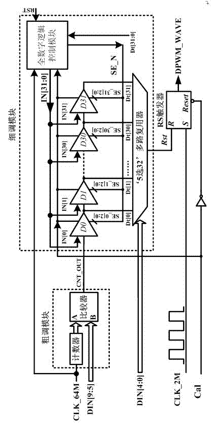
[0040] A digital pulse width modulator (such as figure 2 shown), consists of a coarse-tuning module, a fine-tuning module and an RS flip-flop. The circuit shown in the figure takes 2MHz output frequency and 10bit resolution as an example. The circuit has 4 input ports (2MHz standard clock signal CLK_2M, 64MHz standard clock signal CLK_64M, 10-bit binary DPWM control code DIN[9:0], calibration enable port Cal), one output port (DPWM output DPWM_WAVE), The 2MHz clock signal is obtained by frequency division of the 64MHz clock signal. For the digital pulse width modulator of the invention, it is characterized in that the rough adjustment module is composed of a counter and a comparator; the fine adjustment module is composed of a delay chain (composed of delay units D0~D31), '5 select 32 multiplexes Multiplexer' and full digital logic control module.

...

Embodiment 3

[0064] As a specific application example of the present invention is as follows:

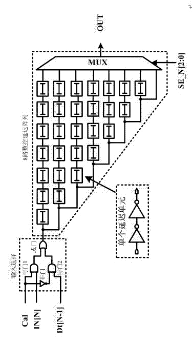
[0065] Such as figure 2As shown, the present invention relates to a binary control digital pulse width modulator circuit including a counter, a comparator, a controllable delay chain, an all-digital logic control module, a '5 to 32' multiplexer and an RS flip-flop. At the initial moment of system operation, the Reset signal is high potential, the Cal signal is high potential, all modules are reset, the delay chain verification starts, and the control code of the digital controllable delay unit is set to '100'. Firstly, by collecting the delay chain port signal Dt[31] and 64MHz pulse, the length of the delay chain transmission delay is judged, and the length of the transmission delay time of the entire delay chain is regulated through the binary code. After adjusting the entire delay chain to reach the target delay time, divide the delay chain into 2 equal parts, 4 equal parts, 8 equal parts an...


PUM


Abstract

The invention discloses a digital pulse width modulator circuit, which belongs to the techncial field of electron. The digital pulse width modulator circuit comprises a coarse tuning module, a fine tuning module and an RS (Remote Sensing) trigger, wherein the coarse tuning module comprises a five-bit counter and a five-bit comparator, and the fine tuning module comprises a delay chain, a 'five-bit 32-circuit selection'multiplexers and an all-digital logical control module. The digital pulse width modulator circuit disclosed by the invention has the advantages that the power consumption is low, the area is small, the accuracy is high, the linearity is high, and the like; and compared with the traditional digital pulse width modulator, according to the digital pulse width modulator circuit disclosed by the invention, finer resolution can be realized without being affected by the variation of technology, temperature and voltage.

Description

[0001] technical field [0002] The invention relates to a digital pulse width modulator circuit, which is used in a digitally controlled DC-DC converter to provide a square wave control signal with a stable duty ratio for a power switching device in a main circuit to control a power device in a Buck converter The switching time belongs to the field of electronic technology. Background technique [0003] In the power conversion circuit of DC output, there are usually two main control methods: analog control and digital control. The digital control loop has many advantages that the analog control method does not have in the DC-DC power converter, such as: the ease of establishment of the digital process, low power consumption, prevention of deviations caused by process and external interference, and so on. The digital control circuit mainly consists of the following parts: Analog-to-Digital Converter (ADC), Digital Compensator (DPID) and Digital Pulse Width Modulator (DPWM)....

Claims


Application Information

Patent Timeline
IPC IPC(8): H03K7/08
Inventor 甄少伟马骁罗萍陈静波贺雅娟张波
Owner UNIV OF ELECTRONIC SCI & TECH OF CHINA
Why Eureka
Try Eureka