Pneumatic thermal loading simulation test device for thermal shielding materials

A thermal protection material and load simulation technology, applied in the direction of material thermal development, can solve the problems of cumbersome operation, high cost, and inability to realize the decoupling analysis of aerodynamic load and thermal load, etc., and achieve simple operation, low cost, and wide adjustment range Effect

Active Publication Date: 2012-12-26
HARBIN INST OF TECH
View PDF4 Cites 27 Cited by
  • Summary
  • Abstract
  • Description
  • Claims
  • Application Information

AI Technical Summary

Problems solved by technology

[0004] At present, the equipment used to characterize and evaluate the aerodynamic thermal load of thermal protection materials is mainly oxyacetylene, arc wind tunnel, and high-frequency plasma wind tunnel. It is difficult to carry out large-scale principled experimental research on aerodynamic and thermal loads, as well as the influence weight of each independent parameter. Therefore, an experimental devic...

Method used


Image

  • Pneumatic thermal loading simulation test device for thermal shielding materials
  • Pneumatic thermal loading simulation test device for thermal shielding materials
  • Pneumatic thermal loading simulation test device for thermal shielding materials

Examples


Embodiment 1

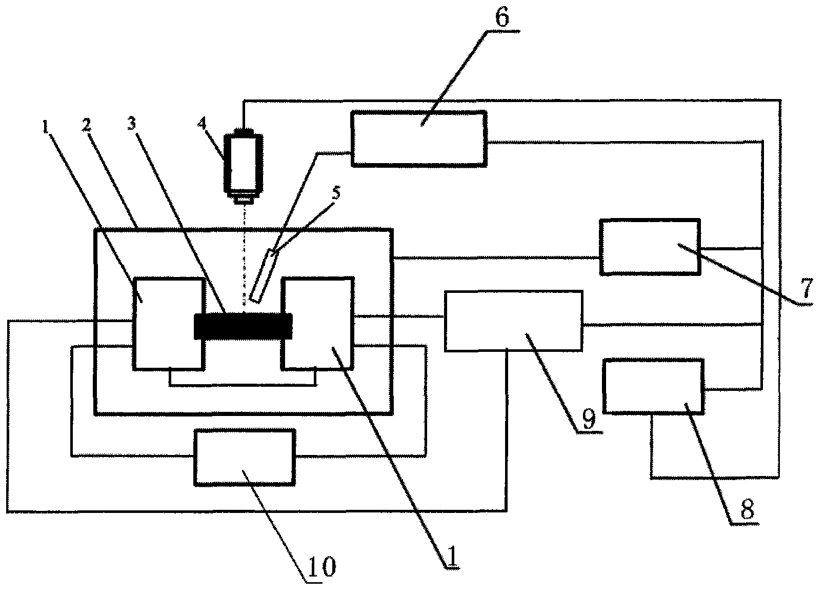
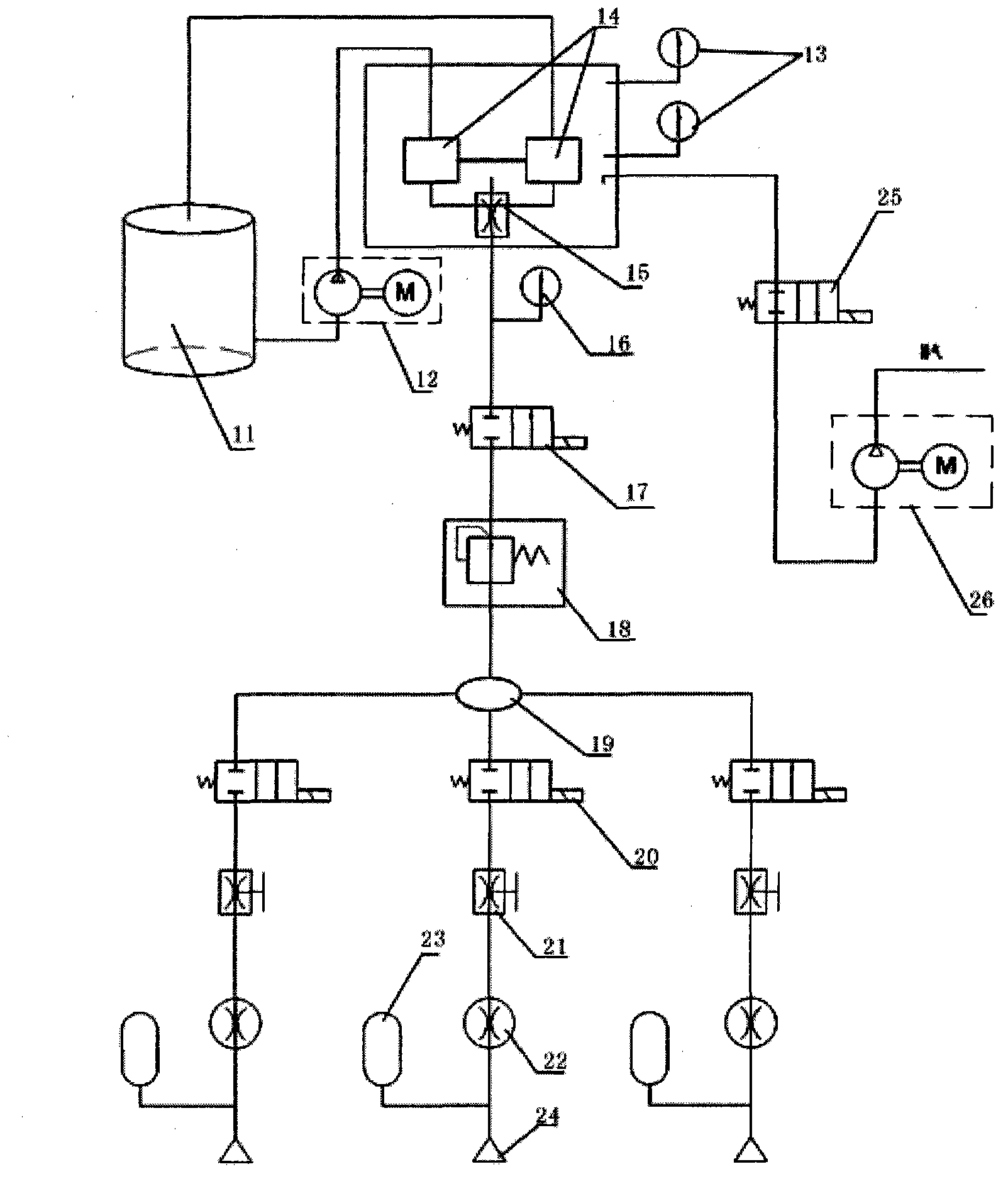
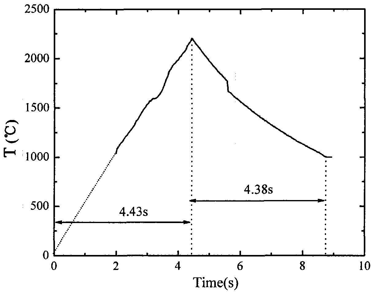
[0032] Using ZrB 2 - The test sample made of 20SiC-10AlN ceramic matrix composite material has a size of 3mm×4mm×36mm, and the surface of the sample is polished to a smoothness of less than 1 μm with diamond abrasive paste. Clamp the polished sample in a copper fixture, the distance from the nozzle to the sample is 5mm, the center of the nozzle coincides with the center of the sample, control the regulating valve and pressure reducing valve, the outlet pressure is 10kPa, the output current is 320A; the surface temperature of the sample 2000±30°C, the heating rate is about 300°C / s, and the loading time is 6.67s.

Embodiment 2

[0034] Using ZrB 2 - The test sample made of 20SiC-10AlN ceramic matrix composite material has a size of 6mm×8mm×36mm, and the surface of the sample is polished to a smoothness of less than 1 μm with diamond abrasive paste. Clamp the polished sample in a copper fixture, the distance from the nozzle to the sample is 5mm, the center of the nozzle coincides with the center of the sample, control the regulating valve and pressure reducing valve, the outlet pressure is 10kPa, the output current is 1170A; the surface temperature of the sample 1800±30°C, the heating rate is about 200°C / s, and the loading time is 9.2s.

Embodiment 3

[0036] Using ZrB 2 -20SiC W The test sample made of ceramic matrix composite material has a size of 6mm×8mm×36mm, and the surface of the sample is polished to a smoothness of less than 1 μm with diamond abrasive paste. Clamp the polished sample in a copper fixture, the distance from the nozzle to the sample is 5mm, the center of the nozzle coincides with the center of the sample, control the regulating valve and pressure reducing valve, the outlet pressure is 40kPa, the output current is 1500A; the surface temperature of the sample 1600±30°C, the heating rate is about 300°C / s, and the loading time is 5.6s.

[0037] The present invention has the following main technical features:

[0038] 1. Monitor the current and voltage output of the device of the present invention through a Hall transformer and a voltmeter: current 0-5000A; voltage 0-10V;

[0039] 2. For thermal protection materials of different materials and structures, the test temperature range of single / double colori...


PUM


Abstract

A pneumatic thermal loading simulation test device for thermal shielding materials comprises a stainless steel environmental chamber, two heating copper electrodes, a single/double colored infrared thermometer, a power supply secondary system, a gas supply secondary system, a vacuum extraction secondary system, a cooling cycle secondary system and a programmable logic controller (PLC) system. The stainless steel environmental chamber is fixed on the ground through supports and insulated from the ground. Three observation windows are arranged on the stainless steel environmental chamber, and the two heating copper electrodes are connected with the power supply secondary system through cables. A gas sprayer is arranged above thermal shielding material samples, and the vacuum extraction secondary system adjusts pressure in the stainless steel environmental chamber. The power supply secondary system is connected with an industrial power wire net. The heating copper electrodes are hollow and connected with the cooling cycle secondary system for cooling in water-cooling mode. The thermal shielding material samples are fixed between the two heating copper electrodes through a copper fixture. The single/double colored infrared thermometer is connected with the PLC system in electric signals mode. The pneumatic thermal loading simulation test device is simple to operate, wide in adjustment range, low in cost, and can be applied to principle researches of pneumatic thermal loading of the thermal shielding materials.

Description

technical field [0001] The invention relates to a ground simulation test device, in particular to a simulation test device for the aerodynamic thermal load simulation test of a high-temperature thermal protection material in a real service environment. Background technique [0002] With the rapid development of aerospace, especially hypersonic, long-term and reusable requirements, the rapid development of hypersonic technology also faces a series of technical problems that need to be solved, including control, propulsion, aerodynamics, structure, and materials. And heat protection, etc., among which breaking through the thermal barrier is the key technical problem that must be solved first in the development of hypersonic vehicles. During the flight in the atmosphere, the hypersonic vehicle interacts with the dense atmosphere. Due to the viscous effect and the strong compression of the shock wave, part of the kinetic energy of the vehicle is converted into the internal energ...

Claims


Application Information

Patent Timeline
IPC IPC(8): G01N25/20
Inventor 孟松鹤金华周印佳易法军许承海
Owner HARBIN INST OF TECH
Why Eureka
Try Eureka