Combined central body cavitating nozzle

A central body and combined technology, which is applied in the direction of injection devices, injection devices, chemical instruments and methods, etc., can solve the problems of discontinuous cavitation jet, inconspicuous cavitation effect, small stagnation area, etc., to achieve erosion and strong blow effect

Inactive Publication Date: 2013-01-02
JIANGSU UNIV
View PDF4 Cites 18 Cited by
  • Summary
  • Abstract
  • Description
  • Claims
  • Application Information

AI Technical Summary

Problems solved by technology

The problems existing in the current nozzles are: (1) As the cavitation nozzles similar to the literature [1] used in the oil drilling industry, there is a cavity in front of the nozzle outlet, and before the fluid flows out of the nozzle, there is a violent impact in the cavity , rebound and vortex, cavitation can occur at the outlet, but the cavitation jet produced by it is discontinuous. If it is applied to cleaning operations, the operating efficiency and operability will be greatly reduced ([1]Jonhnson V E Jr, Conn A F et al. Self-resonating cavitating jets. Proceedings of 6th International Symposium on Water Jet Technology, England, 1982.); (2) As similar to the nozzles studied in [2], the shape of the flow channel near the outlet transitions from the shrinkage of the cross-sectional area to The cross-sectional area suddenly expands. As the fluid is accelerated, the cavitation phenomenon will occur in the low-pressure area and extend downstream. However, in the jet stream generated by it, the cavitation bubbles are mostly concentrated on the periphery of the stream, and the jet fluid and the environmental medium are sheared. Due to the cutting effect, a large number of cavitation bubbles collapse before reaching the surface of the object to be acted on, and cannot erode the surface of the object to be acted upon ([2] Akira Sou, Shigeo Hosokawa, Akio Tomiyama. Effects of cavitation in a nozzle on liquid jet atomization. International Journal of Heat and Mass Transfer, 2007,50:3575-3582.); (3) In the cylindrical central body cavitation nozzle mentioned in [3], the cylindrical central body The raised lower end makes the area of ​​the stagnation zone smaller, and the cavitation effect is not obvious ([3] Yang Minguan, Xiao Shengnan, Kang Can, The influence of outlet shape on the jet performance of the center body nozzle, Fluid Machinery, 2011, Volume 39, Issue 5, 13-19.), while in the triangular central body cavitation nozzle, the two sides of the central body have greater resistance to the incoming fluid, which weakens the impact of the jet

Method used


Image

  • Combined central body cavitating nozzle
  • Combined central body cavitating nozzle

Examples


Embodiment Construction

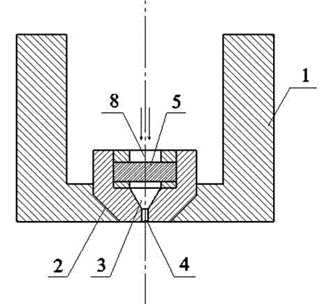
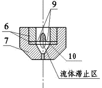
[0012] There is a nozzle jacket 1 connected to the high-pressure system, and the center body 5 is in the shape of a semi-elliptical column. In order to enhance interchangeability, a center body fixing seat 6 is provided. In order to facilitate processing, the fixing seat is divided into upper and lower parts and processed separately. The two parts The inner and outer diameters are the same, the thickness of the lower part is 1 to 3 mm, and the upper part is provided with two oval holes symmetrically along the bottom surface, so that the nozzle can be installed, and the two parts of the fixing seat and the central body are fixed with glue. The central body 5 is horizontally placed on the central body fixed seat 6 perpendicular to the axial direction of the fixed seat. The gap between the central body fixed seat 6 and the central body is a flow passage 9, and the upstream section 8 of the central body is facing the direction of the incoming flow. Place the central body fixing sea...


PUM


Abstract

The invention discloses a combined central body cavitating nozzle and relates to the field of high-pressure water jet nozzles. The combined central body cavitating nozzle comprises a semi-elliptic cylindrical central body, a central body fixing seat and a nozzle seat, wherein the central body has low resistance on the inflowing liquid, the liquid has high energy, after the inflowing liquid enters an internal flow channel of the nozzle, the overflowing section area is suddenly reduced due to the action of the semi-elliptic cylindrical central body, the fluid is accelerated, two strands of high-speed fluid are mixed in a shrinkage channel, inner cavitation bubbles are generated due to the turbulent flow of the central body, the main stream flows out of an outflow straight channel, and peripheral cavitation bubbles are generated due to the shearing functions of the high-speed fluid and air at the outlet. Therefore, the cavitation bubbles are present at the periphery of jet beam and inside the jet beam, and the instantaneous pressure generated by momentum change of high-speed fluid and collapse of the cavitation bubbles generates dual functions on the acted objects. The nozzle has wide high-efficiency working area and good effects of eroding and striking the acted objected.

Description

technical field [0001] The invention relates to the field of high-pressure water jet nozzles, in particular to a center-body type cavitation jet nozzle used in the high-pressure cleaning industry. Background technique [0002] High-pressure water jet technology is a new technology developed in recent years, and it has penetrated into many industries such as mining and machinery manufacturing. At present, the high-pressure jet equipment used in the cleaning of large heat exchangers, train locomotives, and underwater parts of ships has demonstrated their unique advantages. In the process of high-pressure cleaning, after being pressurized by the supercharger, the fluid pressure can reach tens of MPa. When the nozzle outlet diameter is about 1mm, the initial velocity of the jet can reach more than 220 m / s, which has a strong impact force. [0003] The nozzle is a key component of the entire jet system. The shape of the inner flow channel of the nozzle determines the concentrat...

Claims


Application Information

Patent Timeline
Patent Type & Authority Applications(China)
IPC IPC(8): B05B1/34B08B3/02
Inventor 康灿周亮
Owner JIANGSU UNIV
Why Eureka
Try Eureka