

Evaporator for loop heat pipe and application of evaporator
A loop heat pipe and evaporator technology, applied in indirect heat exchangers, circuits, electric solid devices, etc., can solve the problems of increasing the thermal resistance of the evaporation area and reducing the heat transfer performance of the evaporation area
Active Publication Date: 2013-01-02
EAST CHINA UNIV OF SCI & TECH
View PDF5 Cites 6 Cited by
- Summary
- Abstract
- Description
- Claims
- Application Information
AI Technical Summary
Problems solved by technology
On the contrary, the use of materials with low thermal conductivity to make the liquid-absorbing core can suppress the heat leakage in the liquid storage area, so that a higher temperature difference can be obtained on both sides of the liquid-absorbing core, and quick start can be achieved, but it increases the thermal resistance of the evaporation area and reduces the evaporation rate. Zone heat transfer performance
Method used
View moreImage
Smart ImageViewing Examples

Examples
Embodiment 1
[0027] The evaporator of the loop heat pipe that has been installed and welded passes through the steam discharge pipe and the liquid return pipe to form a loop with the finned condenser.
Login to View More PUM
| Property | Measurement | Unit |
|---|---|---|
| thickness | aaaaa | aaaaa |
| porosity | aaaaa | aaaaa |
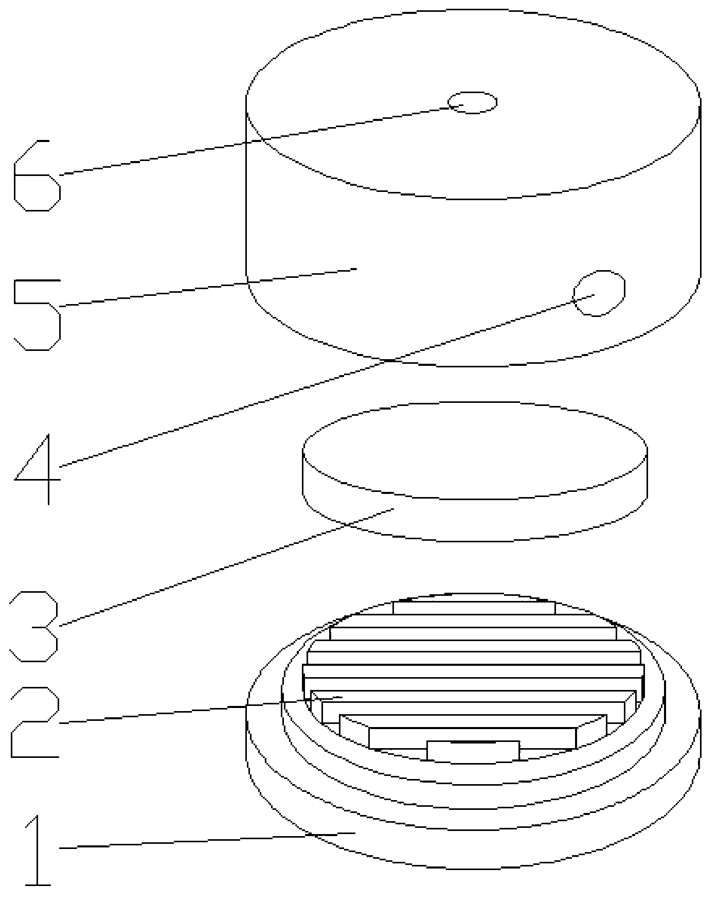
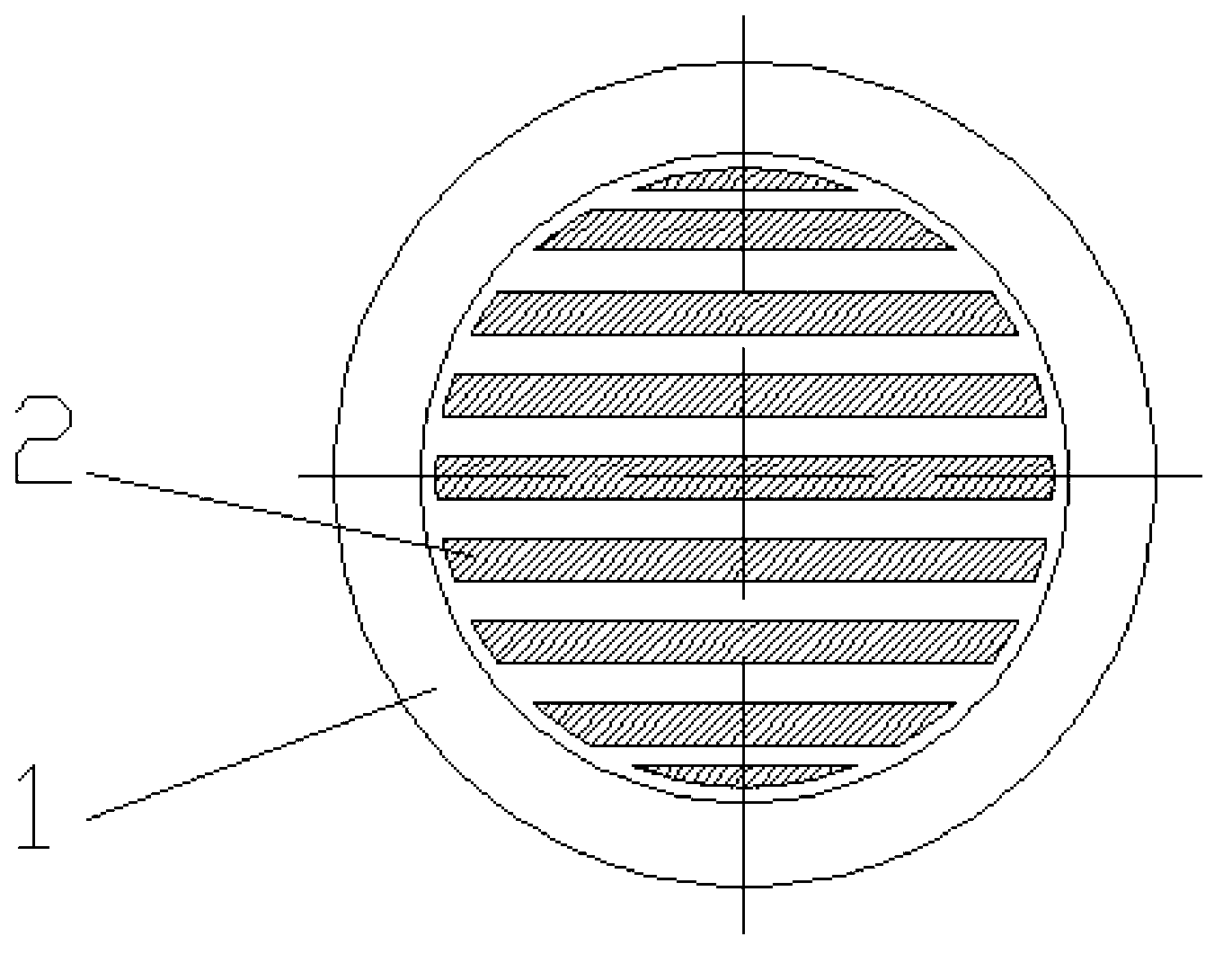
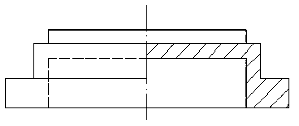
Abstract
The invention relates to an evaporator for a loop heat pipe, and the evaporator comprises a soleplate and an upper cover plate, wherein the soleplate is in welding connection with the upper cover plate; the evaporator is a flat-type evaporator; a copper and nickel dual-layer sintered liquid absorption core is arranged on the upper part of the soleplate; and the liquid absorption core is a copper and nickel dual-layer sintered liquid absorption core, a finished product is divided into an upper layer and a lower layer, and the upper layer is a nickel layer. The evaporator has characteristics of simplicity in design and manufacturing, compactness in structure, low cost and the like; the cooling capacity of the loop heat pipe is enhanced by strengthening the heat conduction and controlling the heat leakage; and the evaporator is applicable to the cooling of an electronic chip with high wasted power.
Description
【Technical field】 [0001] The invention relates to the technical field of evaporators, in particular to an evaporator for a loop heat pipe and its application. 【Background technique】 [0002] With the development of electronic technology, the problem of heat dissipation of chips has become particularly prominent. At present, the most commonly used cooling system for traditional electronic chips is a forced convection air cooling system composed of fins and fans. The ability of this cooling method is extremely limited, the maximum can only provide 1W / cm 2 Excellent heat transfer capability, and the current power dissipation of nearly 200W has reached the limit of air cooling. In order to ensure the working stability and reliability of the chip, reduce the calculation error rate, and make the chip work in an ideal temperature range, it has always been a research hotspot and difficult problem in the field of chip thermal design. The loop heat pipe has the advantages of compac...
Claims
Login to View More Application Information
Patent Timeline
 Patent Type & AuthorityApplications(China)
IPC IPC(8): F28D15/04H01L23/427
Inventor张莉许佳寅徐宏钟杰徐鹏冯缘曾文亮吴松朱成祥
OwnerEAST CHINA UNIV OF SCI & TECH