Laser production process of radio frequency identification antenna

A radio frequency identification and production process technology, applied in the field of electronic radio frequency identification, can solve the problems of limited selection of substrates, complex production process, unstable performance, etc., to achieve easy control of the production process, low requirements for storage conditions, and low-carbon production efficiency Environmentally friendly effect

Active Publication Date: 2013-01-09
SUZHOU ZUENS IOT TECH CO LTD
View PDF8 Cites 12 Cited by
  • Summary
  • Abstract
  • Description
  • Claims
  • Application Information

AI Technical Summary

Problems solved by technology

[0004] 1. Including etching and deinking process, it will produce a lot of waste liquid, and the chemical oxygen consumption of waste liquid is high, which seriously pollutes the environment;
[0005] 2. The production process is complicated, and the production process parameters are not easy to detect and control;
[0006] 3. Heating is required before production starts, and then cooling is required, and high-power equipment such as pumps, drying equipment, and acid gas absorption equipment need to continue to work. The production energy consumption is too large, the production capacity is relatively low, and the production efficiency is low;
[0007] 4. Production equipment is generally large in size and quantity, and needs to occupy a large space;
[0008] 5. The production process needs to use dangerous chemicals such as strong acid, strong alkali, compound glue and ink, which is not conducive to environmental protection and production safety, but also restricts the selection of substrates;
[0009] 6. The utilization rate of raw materials is low;
[0010] 7. The etched antenna is prone to sticking after winding, which requires additional processing;
[0013] 1. The cost of conductive silver paste material is too high;
[0014] 2. The products produced have poor winding and bending resistance, unstable performance, easy oxidation, and are susceptible to environmental factors
[0015] Therefore, the existing radio frequency identification antenna production methods can no longer meet the production needs

Method used


Image

  • Laser production process of radio frequency identification antenna
  • Laser production process of radio frequency identification antenna
  • Laser production process of radio frequency identification antenna

Examples


Embodiment Construction

[0048] The preferred embodiments of the present invention will be described in detail below with reference to the accompanying drawings, so that the advantages and features of the present invention can be more easily understood by those skilled in the art, so as to make a clearer and clearer definition of the protection scope of the present invention.

[0049] See Figure 1 to Figure 18 , The embodiment of the present invention includes:

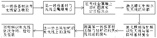
[0050] A laser production process for radio frequency identification antennas, and includes the following steps:

[0051] a) Provide the first substrate;

[0052] b) Spread the adhesive evenly on the first substrate;

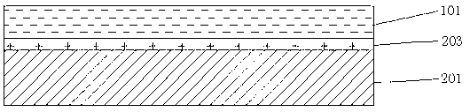
[0053] c) Laminating the first substrate and the antenna metal film 101 through an adhesive;

[0054] d) Use the viscous ink 102 to print an image and several positioning mark points on the antenna metal film 101, and the position of each positioning mark point is determined by referring to the outline of the radio frequency identificati...


PUM


Abstract

The invention discloses a laser production process of a radio frequency identification antenna. The laser production process includes the following steps: (a) providing a first base material; (b) coating adhesives on the first base material; (c) compositing the first base material and an antenna metal film through the adhesives; (d) printing images and a plurality of positioning mark points on the antenna metal film through tacky ink, wherein the position of each positioning mark point is determined with the contour of the radio frequency identification antenna as reference; (e) using laser to grave the contour of the radio frequency identification antenna with the positioning mark points serving as positioning standards; (f) compositing the antenna metal film portion with images after laser graving and a second base material; (g) stripping the second base material and the antenna metal film portion composited with the second base material to form the radio frequency identification antenna and removing waste materials; (h) further removing waste materials on the radio frequency identification antenna; and (i) slitting, detecting and packing the radio frequency identification antenna. The laser production process is environment-friendly, simple in process, low in energy consumption, high in yield and good in stability and safety, and products can be stored easily.

Description

Technical field [0001] The invention relates to the field of electronic radio frequency identification, in particular to a laser production process of radio frequency identification antennas. Background technique [0002] In industrial production, RFID antennas mainly have two production methods: gravure etching and conductive silver paste printing. However, these two production methods have many defects. [0003] The gravure etching production method has the following shortcomings: [0004] 1. Including etching and deinking processes, it will produce more waste liquid, and the chemical oxygen consumption of waste liquid is high, which seriously pollutes the environment; [0005] 2. The production process is complicated, and the production process parameters are difficult to detect and control; [0006] 3. It needs to be heated before the production starts, and then needs to be cooled down, and high-power equipment such as pumps, drying equipment, and acid gas absorption equipment a...

Claims


Application Information

Patent Timeline
Patent Type & Authority Applications(China)
IPC IPC(8): B23K26/36B23K26/42B23K26/362B23K26/70
Inventor 陆凤生
Owner SUZHOU ZUENS IOT TECH CO LTD
Why Eureka
Try Eureka