

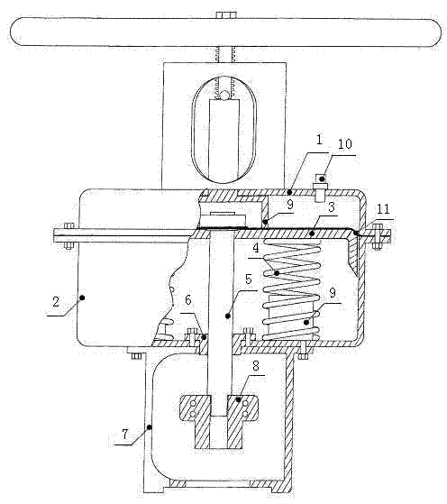
Linear-stroke pneumatic actuator
A pneumatic actuator, straight-stroke technology, applied in the direction of engine components, valve details, valve operation/release devices, etc., can solve the pressure resistance of the sealing ring, the sealing performance cannot meet the actual requirements, and the straight-stroke pneumatic actuator does not work properly Stability, piston and cavity are easy to wear and other problems, to achieve the effect of light weight, simple structure, safe and reliable performance
- Summary
- Abstract
- Description
- Claims
- Application Information
AI Technical Summary
Problems solved by technology
Method used
Image

Examples
Embodiment 1
[0025] Embodiment 1 prepares the used diaphragm of linear stroke pneumatic actuator
[0026] Raw material component parts by weight are as follows:
[0027] 30kg of silica gel, 20kg of nitrile rubber, 15kg of fluorine rubber, 25kg of EPDM rubber, and 5kg of connecting cloth.
[0028] The production method comprises the following process steps:
[0029] Weigh the raw materials; mix the prepared raw materials, the temperature of the rubber mixing is 52°C, and the time is 30 minutes; then fill the refined rubber into the abrasive tool, one layer of rubber and one layer of cloth, until three layers of cloth are loaded; Cover the mold cover and put it into a vulcanizer for vulcanization. The temperature during the vulcanization process is 140°C. After 60 minutes, the vulcanized diaphragm is formed, and the required diaphragm can be obtained after stopping the machine.
[0030] After testing, the working pressure range of the diaphragm in this embodiment is 0.7MPa, the life span i...
Embodiment 2
[0031] Embodiment 2 prepares the used diaphragm of linear stroke pneumatic actuator
[0032] Raw material component parts by weight are as follows:
[0033] 30kg of silica gel, 30kg of nitrile rubber, 25kg of fluorine rubber, 30kg of EPDM rubber, and 10kg of connecting cloth.
[0034] The production method comprises the following process steps:
[0035] Weigh the raw materials; mix the prepared raw materials at a temperature of 55°C for 40 minutes; then fill the refined rubber into the abrasive tool, one layer of rubber and one layer of cloth, until three layers of cloth are loaded; Cover the mold cover and put it into the vulcanizer for vulcanization. During the vulcanization process, the temperature is controlled at 160°C. After 70 minutes, the vulcanized diaphragm is formed, and the required diaphragm can be obtained after stopping the machine.
[0036] After testing, the working pressure range of the diaphragm in this embodiment is 0.62MPa, the service life is up to 3345...
Embodiment 3
[0037] Embodiment 3 prepares the used diaphragm of linear stroke pneumatic actuator
[0038] Raw material component parts by weight are as follows:
[0039] 20kg of silica gel, 20kg of nitrile rubber, 15kg of fluorine rubber, 20kg of EPDM rubber, and 5kg of connecting cloth.
[0040] The production method comprises the following process steps:
[0041] Weigh the raw materials; mix the prepared raw materials, the mixing temperature is 60°C, and the time is 38 minutes; then fill the refined rubber into the abrasive tool, one layer of rubber and one layer of cloth, until three layers of cloth are loaded; Cover the mold cover and put it into the vulcanizer for vulcanization. During the vulcanization process, the temperature is controlled at 150°C. After 50 minutes, the vulcanized diaphragm is formed, and the required diaphragm is obtained after stopping the machine.
[0042] After testing, the working pressure range of the diaphragm in this embodiment is 0.56MPa, the life span i...
PUM
 Abstract
Description
Claims
Application Information