Method for preparing thin film solar cell on mobile phone casing

A technology for solar cells and mobile phone casings, applied to circuits, electrical components, semiconductor devices, etc., can solve the problems of solar chargers being bulky and inconvenient to carry, and solar mobile phone chargers with large volume, so as to reduce man-made pollution and save labor , The effect of simplifying the process

Inactive Publication Date: 2013-01-09
刘莹
View PDF5 Cites 2 Cited by
  • Summary
  • Abstract
  • Description
  • Claims
  • Application Information

AI Technical Summary

Problems solved by technology
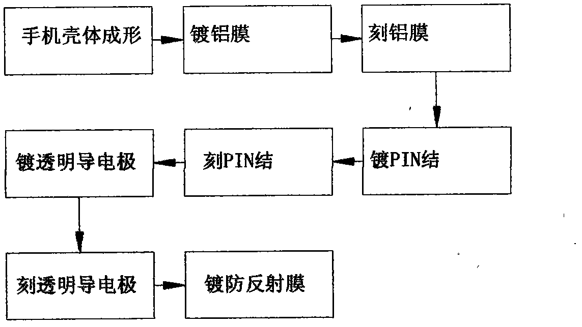
[0003] However, due to the limitation of the conversion efficiency of solar cells, solar mobile phone chargers are often bulky. Compared with smaller and smaller mobile phones with more and more functions, solar chargers are somewhat bulky and inconvenient to carry.

Method used


Image

  • Method for preparing thin film solar cell on mobile phone casing
  • Method for preparing thin film solar cell on mobile phone casing
  • Method for preparing thin film solar cell on mobile phone casing

Examples


Embodiment 1

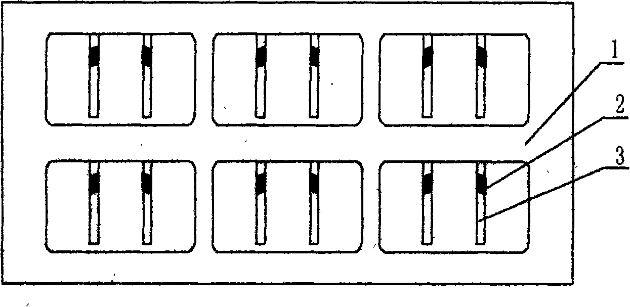
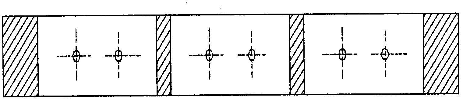
[0026] In this embodiment, a thin-film solar cell is selected to be fabricated on the back shell of a straight mobile phone to illustrate the patent solution. Firstly, the mobile phone shell forming process is carried out. In this process, the lead-out electrodes and bypass diodes are integrated with the mobile phone shell according to the set position, and two through holes are set on one side of the mobile phone shell. A permanent small hole can also be a spare hole, and its diameter is slightly larger than the diameter of the fixture pillar. Wrap the mobile phone case with plastic film, leaving only the back side of the case to be plated. Hang the mobile phone case on the hanger in the independent evaporation vacuum chamber to evaporate the aluminized film. After the process is completed, remove the mobile phone case, remove the film covering the case, and put the mobile phone case into the fixture as designed in the attached figure. When the fixture is put on, you can ben...

Embodiment 2

[0029]In this embodiment, a thin-film solar cell is selected to be fabricated on the back shell of a straight mobile phone to illustrate the patent solution. Firstly, the mobile phone shell forming process is carried out. In this process, the lead-out electrodes and bypass diodes are integrated with the mobile phone shell according to the set position, and two through holes are set on one side of the mobile phone shell. A permanent small hole can also be a spare hole, and its diameter is slightly larger than the diameter of the fixture pillar. Put the mobile phone case into the fixture designed as shown in the attached figure. When the fixture is put on, you can bend the pillar slightly and insert it into the two holes on the side of the mobile phone case, and press against the other side of the case from the inside to clamp the mobile phone case firmly. . Then it is sent to the continuous sputtering aluminum film line. In this process, it is only necessary to put the fixture...


PUM


Abstract

The invention discloses a method for preparing a thin film solar cell on a mobile phone casing. The method mainly comprises the processing steps of: forming a back casing, plating an aluminum film, etching the aluminum film, plating a non-crystal silicon PIN (Personal identification number) junction, etching the PIN junction, plating a transparent conductive electrode, etching the transparent conductive electrode, and plating an anti-reflection film, wherein the back casing forming step adopts a traditional plastic forming method to integrate an output electrode and a bypass diode with the casing; the aluminum film plating step mainly adopts vacuum film plating modes, such as evaporation film plating mode or sputter film plating mode; the non-crystal silicon PIN junction adopts a PECVD (Plasma-enhanced chemical vapor deposition) film plating mode; the transparent conductive electrode adopts the sputter film plating mode; all the three etching processing steps adopt a laser scribing mode; and the anti-reflection film adopts the sputter film plating mode. By utilizing the method disclosed by the invention, a solar cell structure capable of complementing electric energy for a mobile phone cell can be produced in large scale, and the standby time of the mobile phone can be prolonged.

Description

technical field [0001] The invention belongs to the field of solar cell manufacturing, and is particularly suitable for a process method for manufacturing thin-film solar cells on the back shell of a mobile phone to form a compensation circuit. Background technique [0002] The use of solar cells as mobile phone chargers is one of the many applications of solar cells in daily life. It can be easily carried without worrying about being away from the grid, unable to find a suitable socket, etc., and does not need to replace the battery frequently, which is very convenient. [0003] However, due to the limitation of solar cell conversion efficiency, solar mobile phone chargers are often bulky. Compared with smaller and smaller mobile phones with more and more functions, solar chargers are somewhat bulky and inconvenient to carry. [0004] In order to solve the above problems, we can produce a very convenient compensation circuit that can prolong the service life of mobile phone...

Claims


Application Information

Patent Timeline
Patent Type & Authority Applications(China)
IPC IPC(8): H01L31/20
CPCY02P70/50
Inventor 刘莹
Owner 刘莹
Why Eureka
Try Eureka