
Device and process for purifying harmful gas through combining gas-liquid absorption with micro-electrolysis

A harmful gas and process technology, applied in the direction of chemical instruments and methods, dispersed particle separation, separation methods, etc., can solve the problems of micro-electrolysis technology waste gas treatment that have not been seen, and achieve improved absorption effect, large gas volume, and improved absorption capacity Effect

Inactive Publication Date: 2013-01-16
黄立维
View PDF4 Cites 11 Cited by
  • Summary
  • Abstract
  • Description
  • Claims
  • Application Information

AI Technical Summary

Problems solved by technology

There are no reports on the application of micro-electrolysis technology in waste gas treatment

Method used


Image

  • Device and process for purifying harmful gas through combining gas-liquid absorption with micro-electrolysis
  • Device and process for purifying harmful gas through combining gas-liquid absorption with micro-electrolysis
  • Device and process for purifying harmful gas through combining gas-liquid absorption with micro-electrolysis

Examples


Embodiment 1

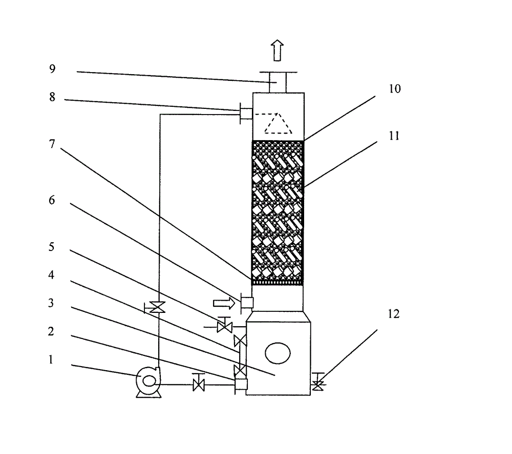
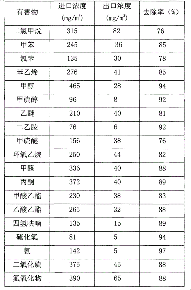
[0015] Example 1: The experimental device system flow is shown in the accompanying drawings. The absorption tower is a packed tower structure, the tower body material is polypropylene, the tower diameter is Ф300mm, and the packing layer height is 2500mm. It is composed of iron Pall rings and activated carbon. Among them, the diameter of the Pall ring is 25mm, and the thickness is 2mm. The diameter of the activated carbon is about 15mm, and the porosity of the filler layer is about 25%. The simulated exhaust gas is introduced from the air inlet at the bottom of the tower, and is discharged from the upper part after passing through the gas-solid-liquid three-phase reaction zone.

[0016] The experimental conditions are: the absorption liquid is 2% sodium chloride aqueous solution + hydrochloric acid. Solution pH=3±0.5.

[0017] Gas flow: 200m 3 / h, gas temperature: 25°C.

[0018] The types of exhaust gas are volatilized with common and representative hydrocarbons, alcohols, ...

Embodiment 2

[0025] Embodiment 2: Experimental device The system flow diagram is shown in the accompanying drawing.

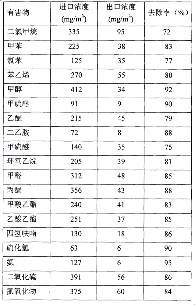
[0026] The experimental conditions are: the absorption liquid is 2% sodium sulfate aqueous solution+sulfuric acid. Solution pH=5±0.5.

[0027] Other conditions are with embodiment 1.

[0028] Experimental results: as shown in Table 2.

[0029] Table 2 Harmful substance removal effect

[0030]


PUM


Abstract

The invention discloses a device and process for purifying harmful gas through combining gas-liquid absorption with micro-electrolysis. The device is composed of an absorption tower, a packing layer and an absorption liquid circulating tank, wherein the packing layer is composed of activated carbon and iron packing. The treatment process is implemented through that: a harmful gas containing airflow to be treated is imported into the device from the lower part of the absorption tower; then, when the harmful gas containing airflow passes through the packing layer composed of activated carbon and iron packing, the harmful gas is effectively absorbed and degraded under the electrode reaction action of multiple micro-batteries formed by the activated carbon and the iron packing; and finally, the purified airflow is discharged from a gas outlet at the upper part of the absorption tower. According to the invention, through adopting a mode of combining liquid absorption and micro electrolytic reaction, the absorption effect is greatly improved, and the possibility of secondary volatilization of harmful substances is also avoided, therefore, the device and process disclosed by the invention are especially applicable to the treatment of harmful gaseous pollutants such as chlorine-containing organic matters, toluene and the like which are poor in water solubility; and the device and process disclosed by the invention are high in treatment efficiency, large in treated gas volume, simple in operation, reliable and practical.

Description

technical field [0001] The invention relates to a gas-liquid absorption combined with micro-electrolysis to purify harmful gas device and its technology, in particular to the removal of volatile organic compounds such as hydrocarbons, alcohols, ethers, aldehydes, phenols, ketones, esters and amines, hydrogen sulfide, sulfur dioxide, etc. The invention discloses a method and a device for inorganic substances such as nitrogen oxides and ammonia, belonging to the technical field of air pollution control and environmental protection. Background technique [0002] Contains volatile organic compounds such as hydrocarbons, alcohols, ethers, aldehydes, phenols, ketones, esters, and amines, and inorganic substances such as hydrogen sulfide, sulfur dioxide, nitrogen oxides, and ammonia, and is produced in various production processes such as chemical, pharmaceutical, painting, and sewage treatment stations. process. These pollutants are not only harmful to the human body, some are ca...

Claims


Application Information

Patent Timeline
Patent Type & Authority Applications(China)
IPC IPC(8): B01D53/78B01D53/18B01D53/32B01D53/04B01D53/70B01D53/72B01D53/48B01D53/52B01D53/60B01D53/58
Inventor 黄立维
Owner 黄立维
Learn More