Bimetallic composite plate material and manufacturing process thereof

A composite sheet and manufacturing process technology, which is applied in the sheet manufacturing process, bimetal composite sheet, and the manufacturing process field of manufacturing the above bimetal composite sheet, can solve the limitation of popularization and application of bimetal composite sheet, reduction of polymer film bonding surface, Unable to guarantee bond strength and other issues, to achieve excellent creep resistance, stable overall performance, and strong bonding

Inactive Publication Date: 2013-01-16
广东晟力新材料有限公司
View PDF15 Cites 9 Cited by
  • Summary
  • Abstract
  • Description
  • Claims
  • Application Information

AI Technical Summary

Problems solved by technology

In this way, it is easy to damage some metal surfaces with special decorative surface layers, or the appearance consistency of products produced under different temperature environments is poor.
Another shortcoming is especially reflected in the application of embossed metal plates. Embossed metal plates have a rich three-dimensional

Method used


Image

  • Bimetallic composite plate material and manufacturing process thereof
  • Bimetallic composite plate material and manufacturing process thereof
  • Bimetallic composite plate material and manufacturing process thereof

Examples


no. 1 example

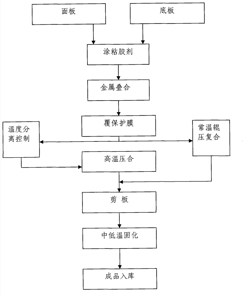
[0043] Include the following steps:

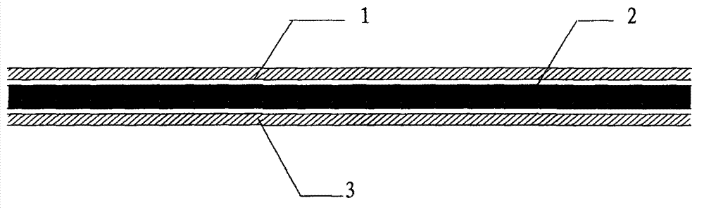
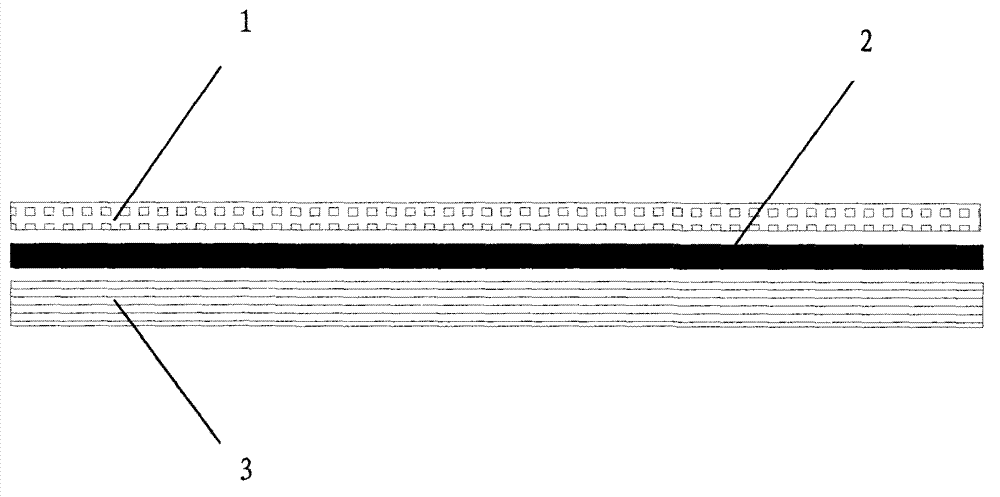
[0044] a. Apply polyurethane adhesive evenly between the surface metal and the bottom metal;

[0045] b. Superimposed surface metal and underlying metal;

[0046] c. Protective film on the opposite metal layer;

[0047] d. The surface layer metal and the bottom metal are rolled together at room temperature;

[0048] e. Cut board;

[0049] f. Curing at low temperature in the range of 35°C-55°C.

no. 2 example

[0051] a. Apply polyurethane adhesive evenly between the surface metal and the bottom metal;

[0052] b. Superimposed surface metal and underlying metal;

[0053] c. Protective film on the opposite metal layer;

[0054] d. Divide 8 heating temperature zones on the upper and lower sides of the composite board, and each two are paralleled as a group of synchronous control, and the group is gradually heated to 80°C for heating and rolling compounding;

[0055] e. Cut board;

[0056] f. Curing at low temperature in the range of 35°C-55°C.

no. 3 example

[0058] a. Apply polyurethane adhesive evenly between the surface metal and the bottom metal;

[0059] b. Superimposed surface metal and underlying metal;

[0060] c. Protective film on the opposite metal layer;

[0061] d. Divide 8 heating temperature zones on the upper and lower sides of the composite board, and each two are paralleled as a group of synchronous control, and the grouping is gradually heated to 100 °C for heating and rolling compounding;

[0062] e. Cut board;

[0063] f. Curing at low temperature in the range of 35°C-55°C.

[0064] The polyurethane adhesive base material described in the above steps is mainly modified polyphenylene oxide (MPPO), supplemented by polystyrene (PS).

[0065] In the process flow, the adhesive is cast and coated on the bimetal composite interface, and under heating and rolling at room temperature or lower than 100°C, sufficient initial bonding force can be produced within 150 seconds to meet the needs of the production process an...


PUM

PropertyMeasurementUnit
Thicknessaaaaaaaaaa
Thicknessaaaaaaaaaa

Abstract

The specification discloses a bimetallic composite plate material and a manufacturing process thereof; the bimetallic composite plate material comprises a surface layer metal and a bottom layer metal; a polyurethane adhesive layer is disposed between the surface layer metal and the bottom layer metal. The manufacturing process of the bimetallic composite plate material comprises the following steps: a. uniformly coating a polyurethane adhesive between the surface layer metal and the bottom layer metal; b. superposing the surface layer metal and the bottom layer metal; c. coating a protection film on the surface layer metal; d. performing normal temperature rolling compounding or heating rolling compounding of the surface layer metal and the bottom layer metal; e. shearing the plate; f. curing at a medium or low temperature.

Description

technical field [0001] The invention relates to a metal plate, in particular to a bimetal composite plate compounded with two metals. [0002] The present invention also relates to a plate manufacturing process, especially a manufacturing process for manufacturing the above-mentioned bimetallic composite plate. Background technique [0003] With social progress and rapid economic development, the contradiction of shortage of various mineral resources is becoming more and more prominent, especially various precious metal resources. In this context, how to use science and technology to improve resource utilization is particularly important. In the architectural decoration industry and light manufacturing industry, there is a huge demand for various metal sheets, such as copper, stainless steel, titanium, titanium zinc, and aluminum. However, in the actual application process, the existing technology is mainly aimed at utilizing the surface material characteristics and thickn...

Claims


Application Information

Patent Timeline
IPC IPC(8): B32B15/01B32B7/12B32B37/06B32B37/12
Inventor 吴旭东林殿雄
Owner 广东晟力新材料有限公司
Why Eureka
Try Eureka