Cooling Structure of Ultra-Precision Linear Motors

A linear motor and cooling structure technology, applied in cooling/ventilation devices, electrical components, electromechanical devices, etc., can solve problems such as heat exchange and side temperature rise, and achieve the effect of suppressing heat exchange and improving thrust density

Active Publication Date: 2015-12-02
HARBIN INST OF TECH
View PDF8 Cites 2 Cited by
  • Summary
  • Abstract
  • Description
  • Claims
  • Application Information

AI Technical Summary

Problems solved by technology

[0006] The purpose of the present invention is to solve the problem that the side temperature of the bilateral surface-mounted cooling structure of the existing linear motor rises and the problem of easy heat exchange with the environment is provided, and a cooling structure for an ultra-precision linear motor is provided.

Method used


Image

  • Cooling Structure of Ultra-Precision Linear Motors
  • Cooling Structure of Ultra-Precision Linear Motors
  • Cooling Structure of Ultra-Precision Linear Motors

Examples


specific Embodiment approach 1

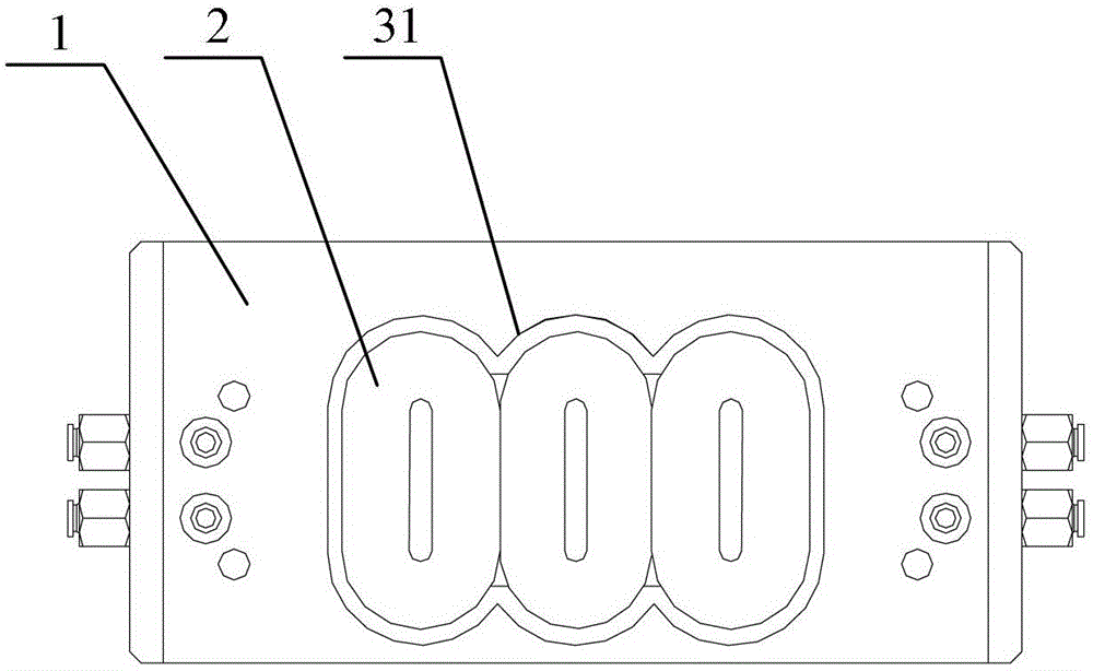
[0025] Specific implementation mode 1: the following combination Figure 1 to Figure 6 To explain this embodiment, the cooling structure of the ultra-precision linear motor described in this embodiment includes a winding support 1 and a winding 2. The winding 2 is fixed on the surface of the winding support 1, and it also includes a heat conduction part, which is arranged on the winding. 2 on the outside surface and fixedly connected with the winding support 1.

specific Embodiment approach 2

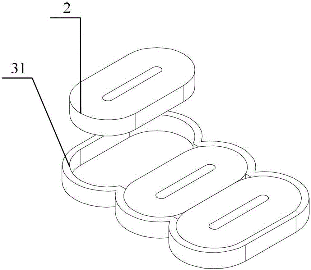
[0026] Specific implementation manner 2: the following combination figure 1 with figure 2 This embodiment is described. This embodiment is a further description of the first embodiment. The heat conducting part is a copper foil ring 31, which is adapted to the outer contour of the winding 2 and is sleeved and fixed on the outside of the winding 2 On the surface.

[0027] In this embodiment, a layer of copper foil ring 31 is added to the side of the winding 2. The copper foil ring 31 and the winding 2 and the winding support portion 1 can be adhered and fixed by structural adhesive respectively. The copper foil ring 31 and the winding The bonding glue between 2 gives priority to high thermal conductivity structural glue. In addition, when assembling, the upper and lower surfaces of the copper foil ring 31 must be in complete contact with the upper and lower water cooling plates, and high thermal conductivity glue can be used to fill in between to ensure that the surface of the c...

specific Embodiment approach 3

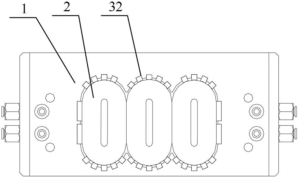
[0029] Specific implementation manner three: the following combination image 3 with Figure 4 This embodiment is described. This embodiment is a further description of the first embodiment. The heat conduction part is a copper foil heat conduction ring 32 composed of a plurality of copper foil sections and arranged dispersedly. The copper foil heat conduction ring 32 is connected to the winding 2 The outer contour is adapted, and each copper foil segment is fixed on the outer surface of the winding 2.


PUM


Abstract

The invention relates to a cooling structure for an ultraprecise linear motor and belongs to the technical field of linear motors. The cooling structure solves the problem of proneness to heat exchange with environment caused by high side temperature of two-side surface-mounted cooling structures of existing linear motors. The cooling structure comprises a winding supporting portion, a winding and a heat conductive portion, wherein the winding is fixed on the surface of the winding supporting portion, the heat conductive portion is arranged on the surface on the outer side and fixedly connected with the winding supporting portion, the heat conductive portion is a copper foil ring which fits the outer profile of the winding and is sleeved and fixed on the surface on the outer side of the winding, or the heat conductive portion is a copper foil heat conductive ring formed by arraying multiple copper foil sections in a dispersed manner, the copper coil heat conductive ring fits the outer profile of the winding, and each copper coil section is fixed on the surface on the outer side of the winding. The cooling structure for the ultraprecise linear motor is suitable for cooling of linear motors.

Description

Technical field [0001] The invention relates to a cooling structure of an ultra-precision linear motor, belonging to the technical field of linear motors. Background technique [0002] The ultra-precision linear motor is an actuator that guarantees the operation of the ultra-precision servo system. With the development of nanotechnology and biotechnology, the requirements for thrust density and thrust accuracy of ultra-precision linear motors have gradually increased, which has brought about an increase in the current density of the motor windings and an increase in copper consumption. Since the current ultra-precision position servo system uses a laser displacement sensor, it has higher requirements for the constant temperature of the ambient temperature. However, due to the high integration density of the ultra-precision servo system, it is difficult to use ultra-precision linear motors during operation. To avoid dissipating heat to the outside world, the ultra-precision posit...

Claims


Application Information

Patent Timeline
Patent Type & Authority Patents(China)
IPC IPC(8): H02K9/00
Inventor 李立毅潘东华熊思亚周悦唐勇斌陈启明郭庆波
Owner HARBIN INST OF TECH
Why Eureka
Try Eureka