Calibration device and calibration method for photoelectric detector

A technology of photodetectors and calibration devices, which is applied in photometry using electric radiation detectors, photolithography exposure devices, micro-lithography exposure equipment, etc., can solve inaccurate calibration results, large environmental pollution of lithography systems, Inconvenient operation and other problems, to achieve the effect of convenient and accurate calibration, improve test accuracy, and improve measurement accuracy

Active Publication Date: 2013-01-23
SHANGHAI MICRO ELECTRONICS EQUIP (GRP) CO LTD
View PDF7 Cites 10 Cited by
  • Summary
  • Abstract
  • Description
  • Claims
  • Application Information

AI Technical Summary

Problems solved by technology

However, the above methods have certain disadvantages: 1. Manually place the absolute detector on the workpiece table, which is inconvenient to operate, low in safety, and increases the complexity of the test; 3. When the absolute detector and the calibrated photodetector are measured separately, it is difficult to ensure that the two measure the light intensity at the same vertical best focal plane. Therefore, in the calibration result, the focal plane The position error causes the error of light intensity measurement to be introduced into the measurement resul

Method used


Image

  • Calibration device and calibration method for photoelectric detector
  • Calibration device and calibration method for photoelectric detector
  • Calibration device and calibration method for photoelectric detector

Examples


Embodiment Construction

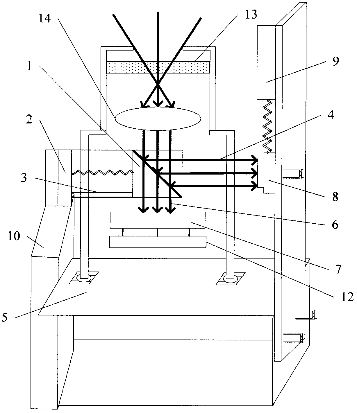
[0041] Specific embodiments of the present invention will be described in detail below in conjunction with the accompanying drawings.

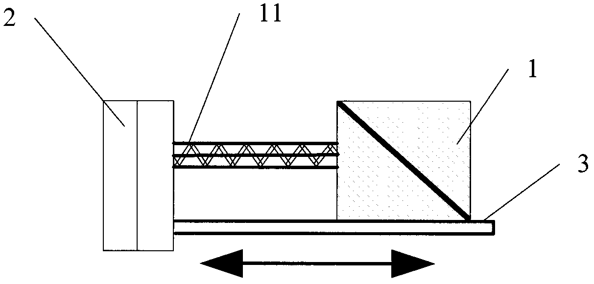
[0042] refer to figure 1 As shown, the photodetector calibration device of the present invention includes a spectroscopic prism 1 and an absolute detector 8, and its calibrated object photodetector 7 is placed on the workpiece table 8 to monitor the actual light intensity of the lighting system, and the output of the lighting system The illuminating light is projected onto the dichroic prism 1, and the dichroic prism 1 reflects and transmits the received light intensity, preferably 50% of the light intensity is reflected and 50% of the light intensity is transmitted; the transmitted light 6 is received by the photodetector 7, And the reflected light 4 is received and sampled by the absolute detector 5 placed on the right. It is also possible to change the setting of the dichroic prism so that the transmitted light is received by the absolute ...


PUM


Abstract

The invention discloses a calibration device and a calibration method for a photoelectric detector. The calibration device comprises a beam splitter prism, an absolute detector and a processing unit; the beam splitter prism is arranged above the photoelectric detector; the photoelectric detector is arranged on a work-piece table; a lighting light is divided by the beam splitter prism into a first measuring light and a second measuring light; the absolute detector is arranged at one side of the beam splitter prism; the second measuring light comes into the absolute detector; the first measuring light comes into the photoelectric detector; the processing unit is used for calculating the light intensity of the second measuring light measured by the absolute detector and the light intensity of the first measuring light measured by the photoelectric detector, building a relation between the photoelectric detector and the absolute detector, and calibrating gain and offset of the photoelectric detector. The calibration device and the calibration method are simple to operate; environmental pollution of a human factor on inside of a photoetching machine is reduced; the test accuracy is improved; and the light measured by the absolute detector and the light measured by the calibration detector are the same light, so that the situation of transmittance change caused by volatility of a light source is avoided, thereby improving the measurement accuracy.

Description

technical field [0001] The invention relates to the field of photoelectric measurement, in particular to a photodetector calibration device and a calibration method thereof. Background technique [0002] In photolithography systems, photodetectors are energy detectors used in the optical system to measure the exposure beam. In general, the lighting system has two beam photodetectors, one inside the lighting system, called the dose detector, which is used to dynamically monitor the beam energy during exposure, and the dose control of many lithography machines is based on the measured value of the dose detector Do feedback control. Another one on the workpiece stage, called a photodetector, measures the field profile and dose when not exposing. [0003] The working principle of the photodetector in the lithography machine is similar to that of the dose detector. They both use special crystals (such as YAG: CE crystals) to convert ultraviolet light into green light, and then ...

Claims


Application Information

Patent Timeline
IPC IPC(8): G03F7/20G01J1/42
Inventor 宋平马明英
Owner SHANGHAI MICRO ELECTRONICS EQUIP (GRP) CO LTD
Why Eureka
Try Eureka