Exhaust gas purifying device

A technology of exhaust gas purification device and catalytic device, which is applied in chemical instruments and methods, dispersed particle separation, separation methods, etc., can solve problems such as damage to the atmospheric environment, and achieve the effect of good purification effect, fast and efficient treatment of exhaust gas, and simple operation.

Active Publication Date: 2013-01-30
东莞市粤丰废水处理有限公司
View PDF4 Cites 20 Cited by
  • Summary
  • Abstract
  • Description
  • Claims
  • Application Information

AI Technical Summary

Problems solved by technology

In this method, the ultraviolet lamp tube irradiates the waste gas to generate active oxygen, which oxidizes the organic matter again, but in the chemical reaction, the active oxygen oxidizes the organic matter is difficult to completely react, and this method generates active oxygen such as ozone mixed in the treated waste gas, The exhaust gas after pollution treatment will destroy the atmospheric environment when discharged into the atmosphere

Method used


Image

  • Exhaust gas purifying device
  • Exhaust gas purifying device
  • Exhaust gas purifying device

Examples


Embodiment 1

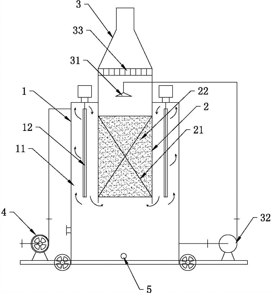
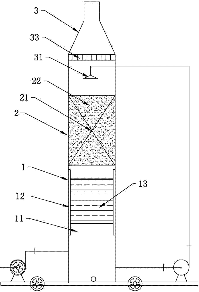
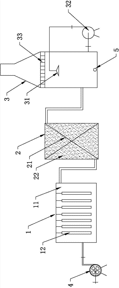
[0031] An exhaust gas purification device, such as figure 1 As shown, including ultraviolet catalytic device 1, ozone treatment device 2 and spray device 3, in the present embodiment, ultraviolet catalytic device 1, ozone treatment device 2 and spray device 3 are all cylindrically arranged, and spray device 3 It is arranged above the ozone treatment device 2 and forms an assembly along the longitudinal direction. The assembly is arranged in the ultraviolet catalytic device 1 and the spray device 3 extends out of the ultraviolet catalytic device 1. The lower end of the ozone treatment device 2 and the ultraviolet catalytic device 1 The gas outlet is connected, and the lower end of the spray device 3 is connected with the upper end of the ozone treatment device 2 .

[0032] In this embodiment, an ultraviolet photolysis chamber 11 for decomposing components in the ultraviolet photocatalytic exhaust gas is formed between the inner wall of the ultraviolet catalytic device 1 and the...

Embodiment 2

[0037] The difference between the exhaust gas purification device of this embodiment and that of Embodiment 1 is that the photocatalyst of this embodiment is a composite catalyst containing transition metal oxides. Other structures and principles of this embodiment are the same as those of Embodiment 1, and will not be repeated here.

Embodiment 3

[0039] The difference between the exhaust gas purification device of this embodiment and that of Embodiment 1 is that the photocatalyst is a photocatalyst containing titanium oxide. Other structures and principles of this embodiment are the same as those of Embodiment 1, and will not be repeated here.


PUM


Abstract

The invention relates to the technical field of exhaust gas treatment, in particular to an exhaust gas purifying device which comprises an ultraviolet catalytic device, an ozone treatment device and a spraying device. A gas outlet of the ultraviolet catalytic device is communicated with a gas inlet of the ozone treatment device, and a gas outlet of the ozone treatment device is communicated with a gas inlet of the spraying device; the ultraviolet catalytic device is provided with an ultraviolet photolysis cavity and an ultraviolet lamp tube arranged in the ultraviolet photolysis cavity, and a photocatalyst is arranged in the ultraviolet photolysis cavity and is irradiated by ultraviolet light of the ultraviolet lamp when exhaust gas is treated; and the ozone treatment device is provided with an ozone decomposition cavity, and the ozone decomposition cavity is provided with a composite catalyst for catalysis of decomposition of ozone. Compared with the prior art, ultraviolet catalyzed photolysis, treatment of residual ozone, spraying of waste solution and absorption of exhaust gas can be combined organically, organic pollutants can be decomposed efficiently, no secondary pollution of ozone can be caused, and the exhaust gas purifying device has the advantages of rapid and efficient treatment of exhaust gas, simpliness in operation and good purifying effects.

Description

technical field [0001] The invention relates to the technical field of exhaust gas treatment, in particular to an exhaust gas purification device integrating ultraviolet photocatalytic decomposition, spray absorption and ozone treatment. Background technique [0002] In recent years, with the development of the economy, a large number of various chemical, coating, furniture, toys, electronics, spraying and other enterprises have emerged, resulting in the emission of a large amount of industrial organic waste gas, which seriously affects the quality of the atmospheric environment and endangers human health. For the treatment of organic waste gas, activated carbon method, condensation method, spray absorption method, etc. are mainly used at present. In recent years, biofilm method, photolysis method and plasma decomposition method have also appeared. However, the exhaust gas adsorption equipment of the conventional activated carbon method is complicated, the adsorbent is easil...

Claims


Application Information

Patent Timeline
Patent Type & Authority Applications(China)
IPC IPC(8): B01D53/86B01D53/78B01D53/76B01D53/72
Inventor 邓杰帆
Owner 东莞市粤丰废水处理有限公司
Why Eureka
Try Eureka