Sand blasting accessory and high-pressure slurry abrasive material jet injection system

An abrasive jet and jet system technology, applied in the fields of cutting, repairing, and slurry abrasive jet cleaning, can solve the problems of inability to quantitatively control the uniformity, limited pressure resistance of the pressure vessel, and limited jet pressure, so as to broaden the effective targeting and feasibility. Controllability, improve work efficiency, and not easy to block the effect

Active Publication Date: 2013-02-13
RONGSHENG KANGJIE BEIJING BIOLOGICAL ENVIRONMENTAL PROTECTION TECH CO LTD
View PDF12 Cites 12 Cited by
  • Summary
  • Abstract
  • Description
  • Claims
  • Application Information

AI Technical Summary

Problems solved by technology

[0006] The technical problem to be solved by the present invention is to provide a sandblasting accessory and a high-pressure slurry abrasive jet injection system, which overcomes the post-mixed dry abrasive water jet in the prior art, and sucks dry abrasive by jet negative pressure, so that the sealed abrasive suction The process produces intermittent airflow to push, the abrasive is in a discontinuous state, the uniformity of the suction cannot be quantitatively controlled, and the ratio of water and abrasive cannot be controlled quantitatively; the abrasive conveying distance cannot be too long; the negative pressure suction of the jet and the intermittent airflow are uncontrollable , uneven, causing the dry abras

Method used


Image

  • Sand blasting accessory and high-pressure slurry abrasive material jet injection system
  • Sand blasting accessory and high-pressure slurry abrasive material jet injection system

Examples


Embodiment Construction

[0025] The principles and features of the present invention are described below in conjunction with the accompanying drawings, and the examples given are only used to explain the present invention, and are not intended to limit the scope of the present invention.

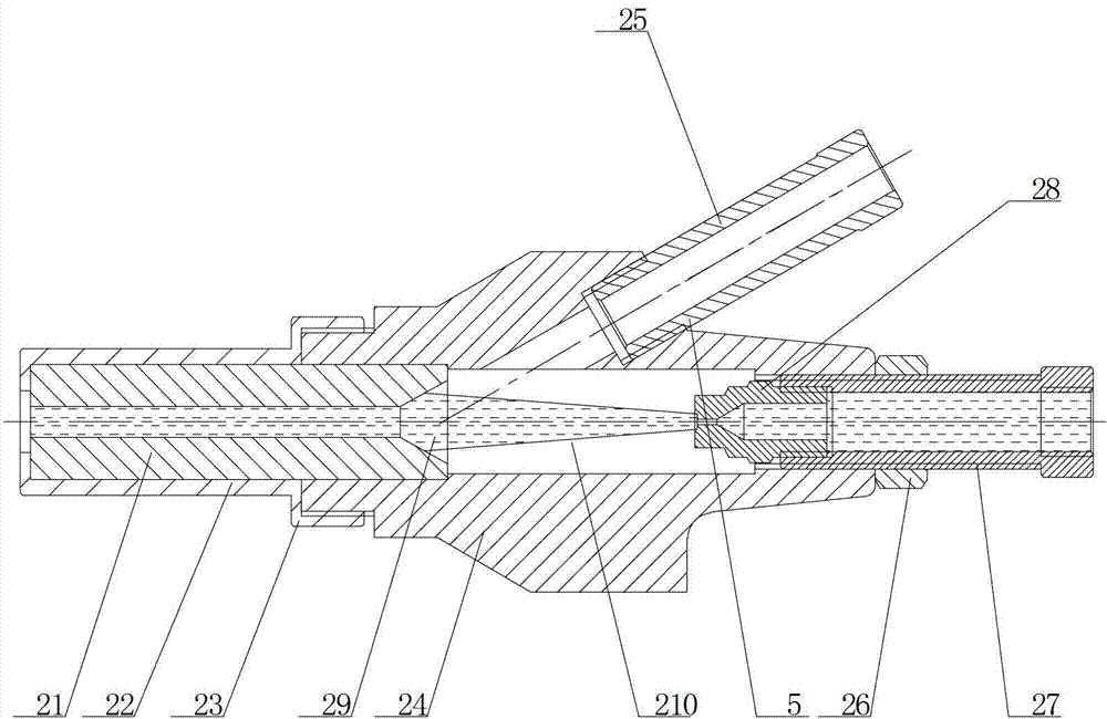
[0026] Such as figure 1 As shown, a sandblasting accessory for a high-pressure slurry abrasive jet injection system of the present invention includes a sandblasting accessory body 24, a high-pressure cylindrical water nozzle 28, a slurry-absorbing abrasive short pipe 25, and the sandblasting accessory body 24 A cavity is arranged inside, and the cavity includes a first cavity 29 and a second cavity 210, the first cavity 29 is a frustum-shaped cavity, and the second cavity 210 is a cylindrical cavity; The bottom surface of the circular platform body-shaped cavity 29 communicates with one end of the cylindrical cavity 210; Cavity; the slurry-absorbing body abrasive short tube 25 is arranged on the upper part of the s...


PUM


Abstract

The invention relates to a sand blasting accessory and a high-pressure slurry abrasive material jet injection system. The sand blasting accessory comprises a sand blasting accessory body, a high-pressure cylindrical water nozzle and a slurry abrasive material sucking stub pipe, wherein a cavity is formed in the sand blasting accessory body and comprises a first cavity and a second cavity; the first cavity is a cone-shaped cavity; the second cavity is a cylindrical cavity; the bottom surface of the cone-shaped cavity is communicated with one end of the cylindrical cavity; the high-pressure cylindrical water nozzle is fixed on the sand blasting accessory body at the other end of the cylindrical cavity, and is communicated with the cavity; the slurry abrasive material sucking stud pipe is arranged on the upper part of the sand blasting accessory body; and slurry abrasive materials jetted by the slurry abrasive material sucking stud pipe and high-pressure water jetted by the high-pressure cylindrical water nozzle are gathered at one end of the cylindrical cavity. By the structure, slurry and water are only required to be mixed at a high-pressure water outlet of the high-pressure slurry abrasive material jet injection system, so that abrasion of a high-pressure nozzle is reduced.

Description

technical field [0001] The invention relates to a sandblasting accessory and a high-pressure slurry abrasive jet injection system, belonging to the fields of slurry abrasive jet cleaning, cutting, repairing and the like. Background technique [0002] Abrasive slurry jet is a slurry made of abrasives, various additives and water in advance, pressurized by a high-pressure pump, and sprays a jet with highly concentrated energy and a very fast speed through the nozzle. This jet acts on the object to achieve surface cleaning. , drilling and mining, material crushing, cutting and other operations. Under the same jet pressure and flow conditions, adding a certain amount of abrasive particles to the water jet can greatly improve the impact ability of the water jet, so that the water jet can perform paint and rust removal under lower pressure. [0003] The structure of the existing post-mixing dry abrasive water jet is that there are high-pressure water focusing nozzles, abrasive sp...

Claims


Application Information

Patent Timeline
IPC IPC(8): B24C9/00B24C5/04B24C3/02
Inventor 谭建忠
Owner RONGSHENG KANGJIE BEIJING BIOLOGICAL ENVIRONMENTAL PROTECTION TECH CO LTD
Why Eureka
Try Eureka