Bending blank manufacturing method for stainless steel flash welding thin-wall ring profiles

A technology of stainless steel and flash welding, which is applied in the field of profile bending of stainless steel flash welding thin-walled rings. It can solve the problems of affecting the dimensional accuracy of rings, ring blanks are easy to produce indentations, and costs a lot, so as to improve dimensional accuracy and processing quality. , The bulging and rounding process is easy, and the effect of saving man-hours and energy consumption

Active Publication Date: 2013-02-27
GUIZHOU ANDA AVIATION FORGING
View PDF4 Cites 4 Cited by
  • Summary
  • Abstract
  • Description
  • Claims
  • Application Information

AI Technical Summary

Problems solved by technology

In the flash welding ring blank prepared by the above method, corners will be formed at the junction of the circular arc part of the ring blank and the straight edge parts at both ends, and indentations will easily occur on the surface of the ring blank; the ring blank is formed into a ring by flash welding After bulging, it is necessary to carry out bulging and rounding treatment. During bulging, stress concentration is likely to occur at the corners and the ring will be swollen and cracked, resulting in the scrapping of the ring. When correcting the circle, it takes a lot of man-hours and energy to trim the corners, and it cannot be completely Elimination, the overall ellipticity of the ring after calibration is large; due to the small machining allowance of the flash welded ring, the large ellipticity of the ring and the indentation on the surface will affect the dimensional accuracy of the ring, resulting in low dimensional accuracy. It is beneficial to obtain flash welding ring parts with less and no allowance processing

Method used


Image

  • Bending blank manufacturing method for stainless steel flash welding thin-wall ring profiles
  • Bending blank manufacturing method for stainless steel flash welding thin-wall ring profiles
  • Bending blank manufacturing method for stainless steel flash welding thin-wall ring profiles

Examples


specific Embodiment approach

[0054] The main chemical element content (percentage by weight) of the alloy is: C content 0.10%-0.16%, Cr content 10.50%-12.00%, Ni content 1.40%-1.80%, W content 1.50%-2.00%, Mo content is 0.35%-0.50%, V content is 0.18%-0.30%, Mn content is ≤0.60%, Si content is ≤0.60%, S content is ≤0.025%, P content is ≤0.030%, and the balance is Fe.

[0055] The specific process steps of bending billet are as follows:

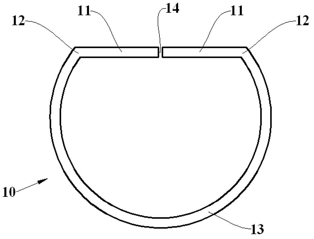
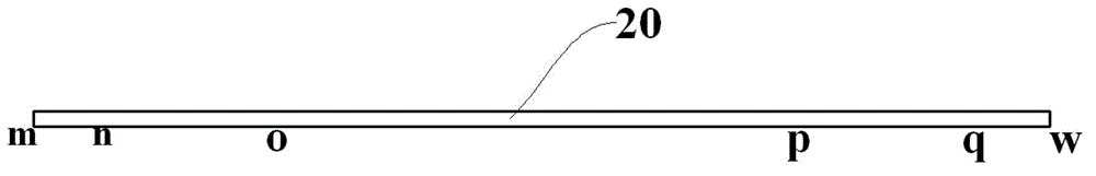
[0056] Step 1: Cut the material. like image 3 As shown, the 1Cr11Ni2W2MoV alloy material with a rectangular cross-section is cut into a profile 20 according to the specifications. The length of the profile 20 is determined according to the diameter of the welding ring, and its maximum cross-sectional area is 65mm (width) × 30mm (thickness). This profile 20 is divided into mn, no, op, pq and qw five sections by m, n, o, p, q, w, in order to make the curvature radius of the op section after bending greater than the curvature radius of the no or pq section and to obtain t...


PUM


Abstract

The invention discloses a bending blank manufacturing method for stainless steel flash welding thin-wall ring profiles. The method comprises the steps that a stainless steel profile fed according to specifications is divided into five segments of mn, no, op, pq and qw, heated to a temperature of 720 DEG C+/-20 DEG C and fed in a bending machine for positioning. The op segment is bent, rotation linear speeds of an upper roller and two lower rollers are 2400 mm/min, the upward moving speeds of the two lower rollers are 10.0 mm/min, the bending is repeated for 3 times, and the op arc segment at this moment achieves a preset curvature radius; and the no segment and the pq segment are bent, the rotation linear speeds of the upper roller and the two lower rollers are 1200 mm/min, the downward moving speeds of the two lower rollers are 12.7 mm/min, the bending is repeated for 3 times, and the no and pq arc segments at this moment achieve preset curvature radii. The profile is bent and deformed into a D-shaped ring blank, two straight sides and an arc portion of the ring blank are connected through a transition arc segment, and phenomena of bent angles at connection positions of the two straight sides and the arc portion and indentations on the surface of the ring blank are eliminated.

Description

technical field [0001] The invention relates to a profile bending method, in particular to a profile bending blank-making method for a stainless steel flash welding thin-walled ring. Background technique [0002] With the increasing demand for rings in industries such as aviation, aerospace, ships, gas turbines, wind energy, nuclear energy, and bearings, rings formed by traditional rolling methods not only waste a lot of materials due to large machining allowances and low material utilization , but also keeps the cost of ring parts high. The ring parts produced by the flash welding process have less machining allowance, high material utilization rate, and greatly reduce the cost, which is conducive to the development of ring forming technology in the direction of precision forming technology. The preparation technology of flash welding ring blank is one of the key technologies for producing flash welding ring parts. [0003] In the prior art, the following methods are main...

Claims


Application Information

Patent Timeline
Patent Type & Authority Applications(China)
IPC IPC(8): B21D7/08B21D7/14
Inventor 欧阳斌魏志坚刘忠赵新石磊邹善垚
Owner GUIZHOU ANDA AVIATION FORGING
Why Eureka
Try Eureka