
Equipment for steel slag air quenching and waste heat recycling

A waste heat recovery and steel slag technology, which is applied in the field of converter steel slag treatment equipment, high temperature steel slag treatment and heat recovery in converter steelmaking, can solve the problems of high temperature slag particle collection, loss of simple iron element, uneven feeding, etc. The effect of small land area, improved mobility, and reduced investment

Active Publication Date: 2013-03-06
唐钢国际工程技术有限公司
View PDF5 Cites 6 Cited by
  • Summary
  • Abstract
  • Description
  • Claims
  • Application Information

AI Technical Summary

Problems solved by technology

[0004] (1) The problem of the loss of elemental iron in steel slag
After the steel slag is tapped, the steel slag contains some elemental iron elements. Due to its high temperature, which can reach 1400°C, it will inevitably be oxidized and become Fe in the process of direct contact with air or water. 2 o 3 Or FeO, causing a serious waste of resources
[0005] (2) Dust or steam
In the usual slag, magnetic separation or water quenching process, a large amount of smoke or water vapor will inevitably be generated, causing environmental pollution
[0006] (3) Collection of high temperature slag particles
[0007] (4) Nitrogen consumption
[0008] (5) Pressure release problem in the equipment
[0010] (7) Uneven feeding
If a slag cooler is used, only about 80°C hot water can be obtained, and the quantity is astonishing, requiring huge cooling water equipment

Method used


Image

  • Equipment for steel slag air quenching and waste heat recycling
  • Equipment for steel slag air quenching and waste heat recycling
  • Equipment for steel slag air quenching and waste heat recycling

Examples


Embodiment Construction

[0045] The present invention uses nitrogen as the gas source for quenching and cracking, grate cold conveyor 3 and high temperature resistant bucket elevator 4 as conveying equipment, circulating fluidized bed waste heat boiler 5 as sensible heat recovery equipment, and adopts steel slag gas quenching and waste heat recovery process.

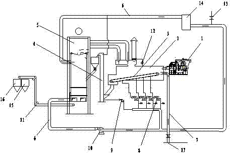
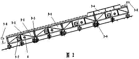
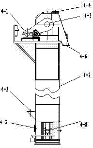
[0046] The equipment of the present invention includes an air quenching slag tank 1, a granulation wind tunnel 2, a grate cold conveyor 3, a high temperature resistant bucket elevator 4, a circulating fluidized bed waste heat boiler 5, a nitrogen circulation pipeline 6, and an external nitrogen pipeline 7.

[0047] The figure shows that the slag outlet of the air-quenching slag tank 1 is connected with the slag inlet of the granulation wind tunnel 2, and the granulation wind tunnel 2 is connected with the grate cold conveyor 3. The lower part of the granulation wind tunnel 2 is a slope-shaped structure. The lower port of the granulation wind tunn...


PUM


Abstract

Equipment for steel slag air quenching and waste heat recycling belongs to the technical field of the steel slag processing equipment and method. Steel slag air quenching and waste heat recycling processes are utilized to treat high-temperature steel slags and recovering heat; and the technical scheme is as follows: in the equipment, an air quenching slag pot is connected with a pelletization air tunnel which is connected with a grate cooling conveyor; the grate cooling conveyor is connected with a high-temperature-resistant bucket elevator; the high-temperature-resistant bucket elevator is connected with a circulating fluidized bed heat recovery boiler; an external nitrogen pipeline is connected with the pelletization air tunnel and the grate cooling conveyor, respectively; and a nitrogen circulating pipeline is connected with the high-temperature-resistant bucket elevator and the circulating fluidized bed heat recovery boiler, respectively. The process flow comprises hardening and cracking liquid-state steel slags into even particles by using low-temperature nitrogen, and then feeding the steel slag particles to the circulating fluidized bed heat recovery boiler through pneumatic transmission so as to collect waste heat and zero-valent iron. The integrated steel slag air quenching process provided by the invention is in a world leading level and is innovation of liquid-state steel slag treatment and heat recovery, thereby having wide prospect.

Description

technical field [0001] The invention relates to equipment and a method for processing high-temperature steel slag in converter steelmaking and recovering heat, and belongs to the technical field of converter steel slag treatment equipment and methods. Background technique [0002] The treatment of high-temperature steel slag in converter steelmaking is a necessary link in the production of converter steelmaking. The cold disposal method and hot pouring method used in the past are due to large investment, large area occupation, serious environmental pollution, and many process equipment and production operators. Disadvantages have now been eliminated. The plate-splashing water-cooling method has cumbersome process, many links, high operating costs and waste of water, which is an outdated process. At present, the water quenching method and the wind quenching method are more widely used. The disadvantage of the water quenching method is that the sensible heat of steel sla...

Claims


Application Information

Patent Timeline
IPC IPC(8): C21B3/04C21B3/06C21B3/08C21C5/46F27D17/00
CPCC21B2400/026C21B2400/06C21B2400/076C21B2400/08Y02P10/20Y02P10/25Y02W30/50
Inventor 张景波董文进安连志曹寿君
Owner 唐钢国际工程技术有限公司
Learn More