Assembling method for liquid storage device and compressor

An assembly method and compressor technology, applied in the field of compressors, can solve problems such as high cost, complicated assembly process, and easy gas leakage, and achieve the effects of simple structure, reduced welding material consumption, and reduced labor intensity

Active Publication Date: 2015-07-01
DONGGUAN JINRUI HARDWARE PROD
View PDF7 Cites 1 Cited by
  • Summary
  • Abstract
  • Description
  • Claims
  • Application Information

AI Technical Summary

Problems solved by technology

[0008] The purpose of the present invention is to address the deficiencies of the prior art, and provide a method for assembling the liquid accumulator and the compressor, which is convenient in processing, improves production efficiency, ensures welding effect, and avoids complicated assembly procedures and easy leakage of gas in the prior art , high cost and other defects

Method used


Image

  • Assembling method for liquid storage device and compressor
  • Assembling method for liquid storage device and compressor
  • Assembling method for liquid storage device and compressor

Examples


Embodiment 1

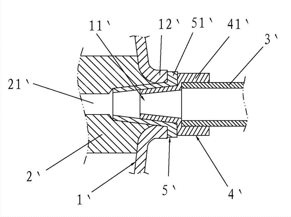
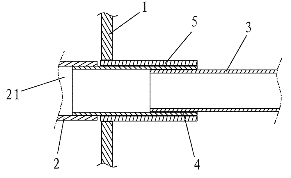
[0036] Such as Figure 4 , Figure 5 As shown, the method for assembling the liquid accumulator and the compressor of this embodiment includes the following steps:

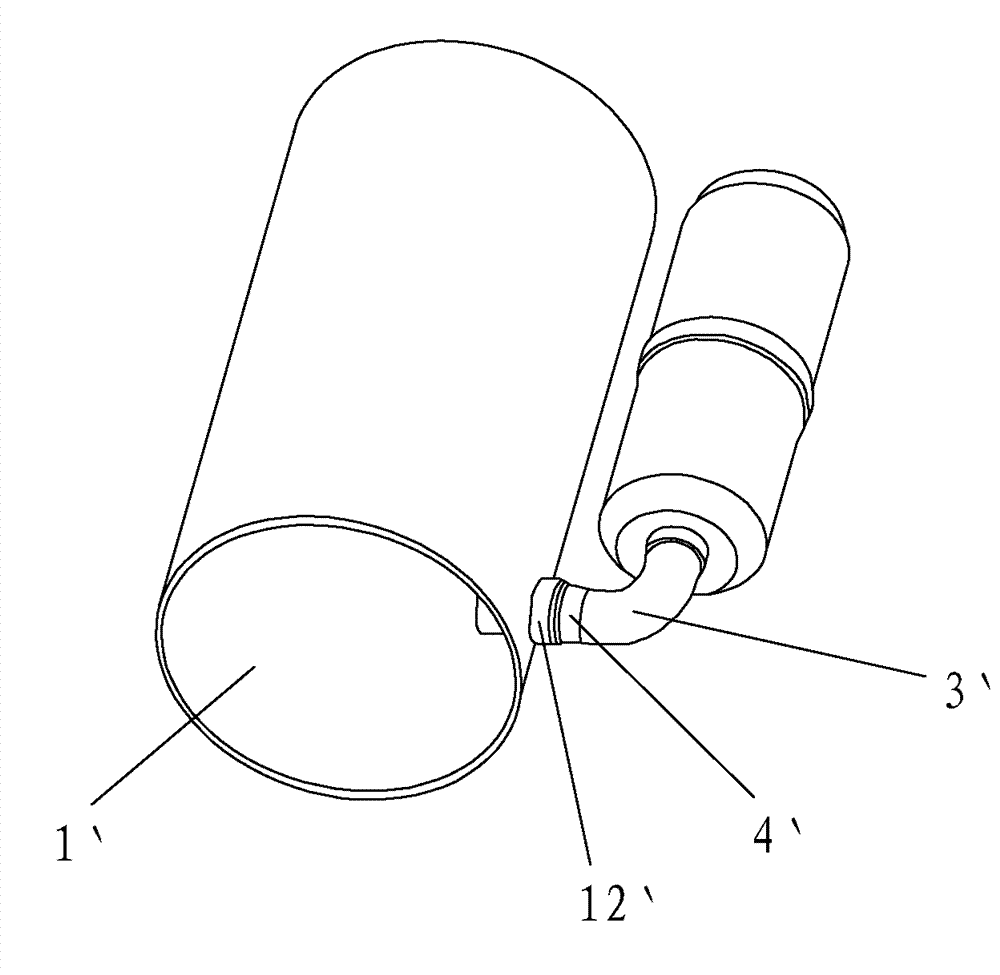
[0037] a. A through hole 11 is provided on the side of the shell 1 of the compressor. The edge of the through hole 11 is provided with a flanging 12. The flanging 12 can be formed by stamping. The angle between the flanging 12 and the intake pipe 3 is 0-90° °, the included angle being 0-90° means that the shape of the flanging 12 is a trumpet shape that flares outwards, and the flanging 12 of the trumpet shape is convenient for the air intake pipe 3 to be inserted into the through hole 11, and is also convenient for aligning the flanging 12 with the air intake pipe. 3 welding, the diameter of the through hole 11 is greater than the outer diameter of the intake pipe 3, and the housing 1 is made of steel;

[0038] b. Set the cylinder 2 in the housing 1, the air inlet 21 of the cylinder 2 is in the same direction a...


PUM


Abstract

The invention relates to the technical field of compressors, in particular to an assembling method for a liquid storage device and a compressor. The assembling method comprises the steps that a through hole is formed in a side surface of a housing; a flange is formed at the edge of the through hole; the diameter of the through hole is greater than the outer diameter of an air inlet pipe; an air cylinder is placed in the housing; a first end of the air inlet pipe penetrates the through hole and is pressed into an air inlet of the air cylinder; a seal groove is formed at the air inlet and internally provided with a seal ring; the seal ring is connected with a side wall of the air inlet pipe in a sleeving manner; and the flange is welded with the air inlet pipe along the excircle of the air inlet pipe after the air cylinder is fixed in the housing. According to the assembling method, the air inlet pipe is connected with the housing directly, refrigerant gas enters the air cylinder directly through the air inlet pipe and passes through few parts; and the seal ring is arranged between the air inlet pipe and the air inlet of the air cylinder, so that leakage is avoided. As the air inlet pipe is fixed by the flange, the structure is simple; the assembling is convenient; welding positions are few; the welding material consumption and the labor intensity can be reduced; and the production efficiency can be improved.

Description

technical field [0001] The invention relates to the technical field of compressors, in particular to an assembly method of a liquid accumulator and a compressor. Background technique [0002] The compressor is a fluid machine that raises low-pressure gas to high-pressure gas. It is the heart of the refrigeration system. There is a cylinder inside the shell of the compressor. When working, the low-temperature and low-pressure refrigerant gas enters the cylinder from the intake pipe, and the cylinder After it is compressed, high-temperature and high-pressure refrigerant gas is discharged from the exhaust pipe to provide power for the refrigeration cycle, thereby realizing the refrigeration cycle of compression→condensation→expansion→evaporation. During the operation of the system, it is impossible to guarantee that the refrigerant can be completely vaporized during the evaporation stage. In order to avoid the liquid refrigerant coming out of the evaporator from entering the cy...

Claims


Application Information

Patent Timeline
Patent Type & Authority Patents(China)
IPC IPC(8): B23P11/00B23K9/16B23K1/00B23K11/00B23K20/12B23K13/00F04B39/00
Inventor 陈金龙
Owner DONGGUAN JINRUI HARDWARE PROD
Why Eureka
Try Eureka