System for automatically draining water on side slope and method therefor

An automatic drainage and side slope technology, which is applied in excavation, soil protection, construction, etc., can solve the problems of inability to supplement drainage holes, high drilling cost, and difficulty in implementation, and achieves low production cost, good drainage effect, and hydrophobicity. low cost effect

Inactive Publication Date: 2013-03-13
UNIV OF SCI & TECH BEIJING
View PDF7 Cites 14 Cited by
  • Summary
  • Abstract
  • Description
  • Claims
  • Application Information

AI Technical Summary

Problems solved by technology

The first method is a commonly used drainage method. Its disadvantage is that the construction cost is high, and drainage holes must be constructed in time during the formation of the slope. If the optimal construction period is missed, once the slope is formed, there is no operating platform. It is impossible to add drainage holes. The second method is suitable for slope drainage where the distance between the slope surface and the drainage area is relatively long, the drainage distance of the horizontal hole is too long, and the construction is extremely difficult; or there is water seepage in the later stage of slope excavation. It is difficult for personnel and equipment to work on the steep slope that has been formed, and it can only be constructed in the area of ​​the slope step
The disadvantages of using vertical holes for drainage are as follows: (1) Usually, submersible pumps are used to pump out the accumulated water seeping from the drainage holes. Not only does it take a lot of manpowe

Method used


Image

  • System for automatically draining water on side slope and method therefor
  • System for automatically draining water on side slope and method therefor
  • System for automatically draining water on side slope and method therefor

Examples


specific Embodiment 1

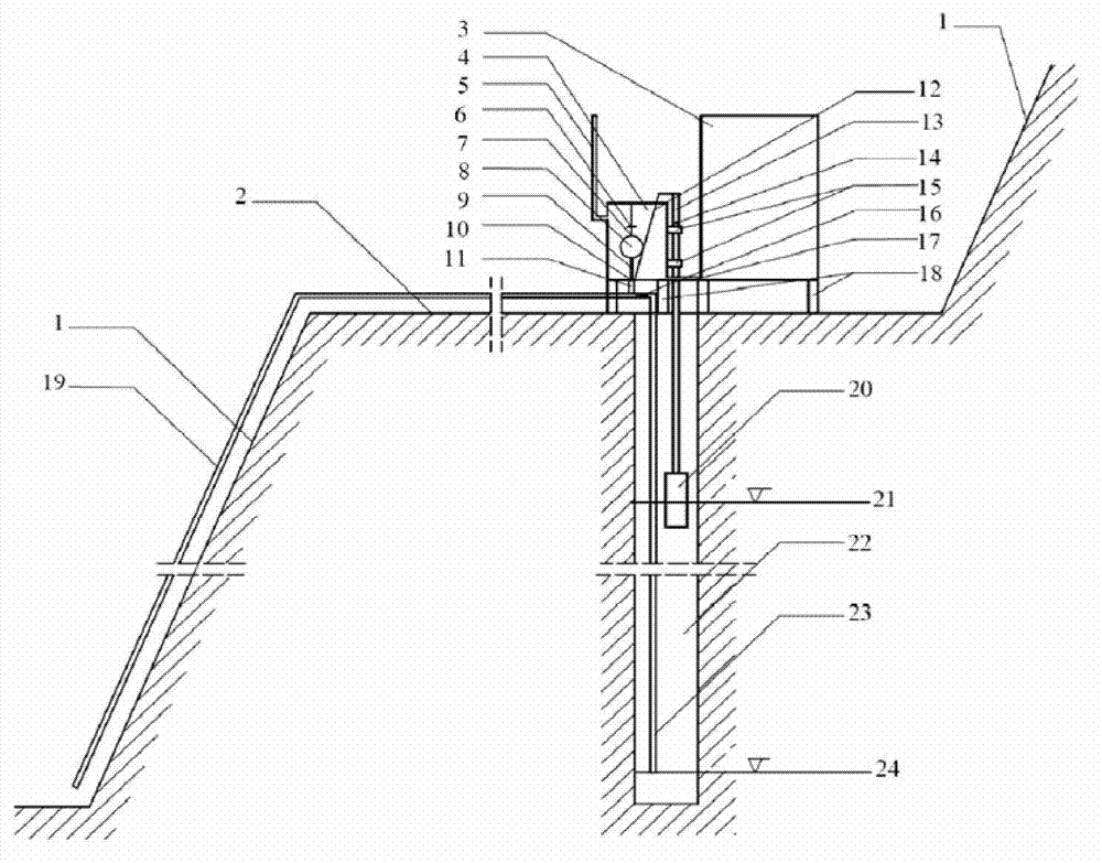
[0039] Figure 1-3 Schematic diagram of the slope drainage system. The slope automatic drainage system mainly includes three major devices: energy storage device, trigger device and drainage device.

[0040] As shown in the figure, the energy storage device includes a water storage tank 3, an energy storage tank 4, a communication pipe 17 between the energy storage tank 4 and the water storage tank 3, and a water outlet pipe 11 communicated with the drain pipe 19. In addition, in order to ensure energy storage The water flow in the tank 4 can be smoothly discharged and inflowed, and an air inlet pipe 5 which is positioned on the energy storage tank and communicated with the atmospheric pressure can also be arranged in the energy storage device.

[0041] The triggering device includes a suspension cylinder 20, a rigid buoy rod 13, a guide cylinder 15, an elastic connecting rope 12, a limit card 6, a limit nut 14, a guide rod 7, a floating ball 8, and a rigid pressure rod 9.

...

specific Embodiment 2

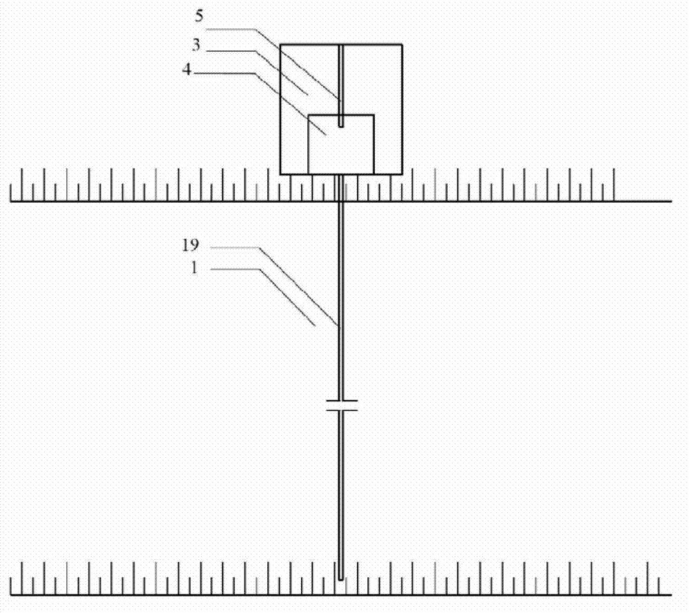
[0059] In order to realize the automatic drainage of multi-level slopes, a multi-stage automatic drainage system can be formed by the automatic drainage systems of the slopes in the first embodiment, and the drainage pipe 19 of the automatic drainage system of the upper step can be connected with The water storage tank 3 of the side slope automatic drainage system of the next step is connected to each other to replenish the water consumed in the latter water storage tank 3, so as to realize the step-by-step downward discharge of accumulated water on the side slope. At the same time, an overflow pipe is set at the water storage tank 3 of the automatic drainage system of the second level (sorted from top to bottom) steps and the automatic drainage system of the lower steps, to ensure that the water discharged from the upper level drain pipe 19 is filled with this After the water storage tank 3, it flows to the set final water storage location through the overflow pipe.

[0060] ...

specific Embodiment 3

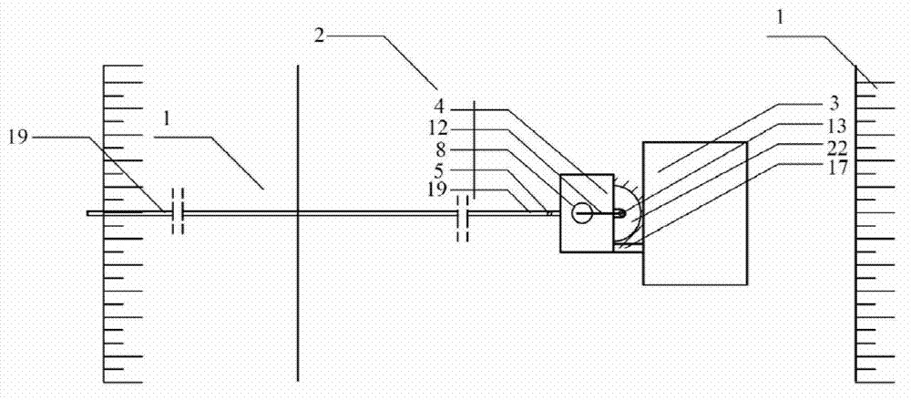
[0062] Figure 4 , Figure 5 , Figure 6 , Figure 7It is a schematic diagram of the drainage action of the slope automatic drainage system. A specific example of the on-site drainage application of the slope automatic drainage system in the present invention will be described below in conjunction with the accompanying drawings.

[0063] When the water level in the catchment borehole 22 reaches the automatic drainage starting water level 21, the slope drainage system placed on a certain open-air slope step is activated, and finally the drainage system has a siphon phenomenon, and the accumulated water in the catchment borehole 22 is pumped out. To achieve the purpose of automatically draining the accumulated water on the slope.

[0064] The specific implementation process is as follows:

[0065] Step 1. System initialization. Before the automatic drainage system is started, the energy storage tank 4 is filled with water, and the floating ball 8 and the rigid pressure rod...


PUM


Abstract

The invention provides a system for automatically draining water on a slide slope and a method therefor. The system comprises an energy storing device, a triggering device and a drainage device, wherein the energy storing device comprises a water storage tank, an energy storage tank, a water outlet pipe, a water stopping plug and the like; the triggering device comprises a suspension cylinder, a rigid suspension cylinder rod, a guide cylinder, an elastic connecting rope, a guide rod, a floating ball, a rigid pressing rod and the like; and the drainage device comprises a water pumping pipe, a drainage pipe and the like. The system is placed at the upper portion of a converging hole of a step of the side slope, when a water level in the converging hole reaches a designed automatic drainage starting water level, the triggering device is started, the water stopping plug is opened, water stored in the energy storage tank flows into the drainage pipe, and when the drainage pipe is filled with the stored water and the water stopping plug is closed, a siphonage phenomenon appears in the system, and accumulated water in the converging hole is discharged to the lower portion of the side slope through the water pumping pipe and the drainage pipe. According to the system, the structure is simple, energy sources such as electric energy, solar energy and wind energy are not required, the system is provided with no precise component or quick-wear part, good adaptability for drainage of various side slopes in the wild is achieved, drainage construction is achieved, the management is simple, the cost is low, and the drainage effect is good.

Description

technical field [0001] The present invention relates to an automatic drainage system, in particular to an automatic drainage system for slopes that can be applied to drain open-air slopes, road and railway slopes, and hydropower slopes to realize the automatic drainage of slopes. . Background technique [0002] Open-air slopes, road and railway slopes, etc. are often rich in a large amount of accumulated water. The sources mainly include rainwater infiltration, upper slope or mountain water infiltration, and even stream water infiltration. The accumulated water in the slope is very unfavorable to the stability of the slope, mainly in the following aspects: (1) The strength of the general rock in the dry state is often 1-2 times that of the saturated state, so the stability of the dry slope is obviously higher than that of the rock. Water-bearing slope; (2) Many rocks such as granite porphyry, mudstone, argillaceous conglomerate, and montmorillonite have the characteristics ...

Claims


Application Information

Patent Timeline
IPC IPC(8): E02D3/10E02D17/20
Inventor 韩斌吴爱祥胡凯建韩思愉王贻明王洪江尹升华仪海豹于少峰
Owner UNIV OF SCI & TECH BEIJING
Why Eureka
Try Eureka