Variable vehicle lift mechanism of engine

An engine and variable technology, applied in the direction of mechanical equipment, engine components, machines/engines, etc., can solve the problems of engine 1 cost increase, difficulty increase, engine power loss, etc.

Inactive Publication Date: 2013-03-13
KYMCO
View PDF6 Cites 6 Cited by
  • Summary
  • Abstract
  • Description
  • Claims
  • Application Information

AI Technical Summary

Problems solved by technology

Because the first and second rocker arms 21, 22 are made of heavy cast iron material, the moment of inertia is relatively large, so the force of the valve spring 23 also needs to be set stronger to overcome the moment of inertia. , which also makes the engine power loss larger; in addition, the second rocker arm 22 is a multi-link structure, because of its complex structure and a considerable operating space wh...

Method used


Image

  • Variable vehicle lift mechanism of engine
  • Variable vehicle lift mechanism of engine
  • Variable vehicle lift mechanism of engine

Examples


Embodiment Construction

[0063] Relevant structure of the present invention and the effect that can be achieved are described as follows in conjunction with drawings:

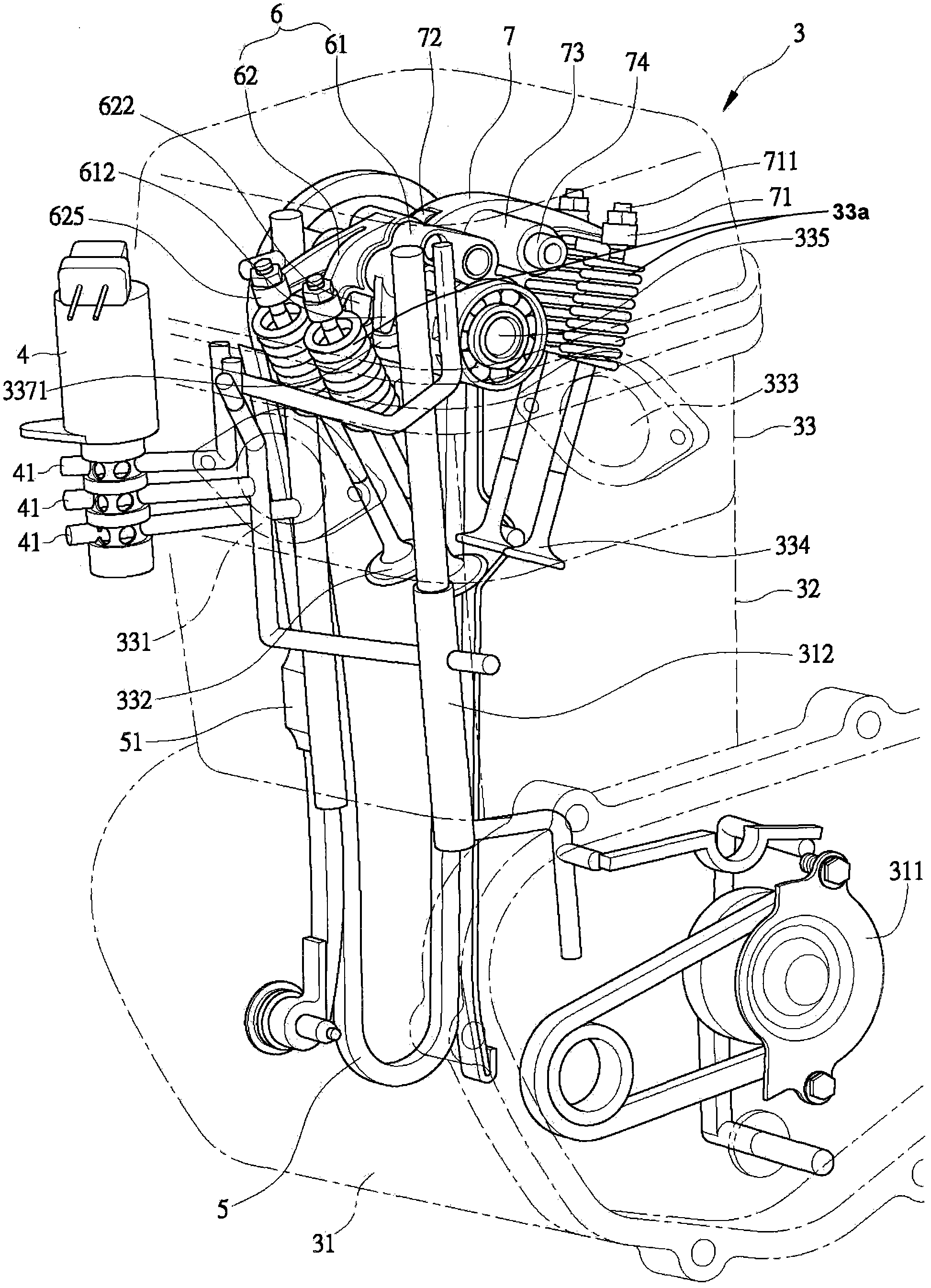
[0064] see figure 2 Shown, engine 3 of the present invention has a crankcase 31, one group is located at the cylinder body 32 on the crankcase 31, one group is located at the cylinder head 33 on the cylinder body 32; This crankcase 31 is provided with a crankshaft ( Not shown in the drawing), and an oil pump 311, the oil pump 311 sends the oil to a main oil supply passage 312, and the main oil supply passage 312 is communicated with the crankcase 31 through the cylinder body 32 to be arranged on The oil control valve 4 of the cylinder head 33; the cylinder body 32 is arranged on the top of the crankcase 31, and can pass through the timing chain 5, wherein, the cylinder body 32 is provided with a positive When the chain tensioner 51.

[0065] The cylinder head 33 is provided with an intake port 331 and an intake valve 332 on the inta...


PUM


Abstract

The invention discloses a variable vehicle lift mechanism of an engine. An air intake/exhaust pier, an air intake/exhaust valve, a cam shaft base and a cam shaft are arranged on a cylinder head of the engine; a long air intake cam, a short air intake cam and an air exhaust cam are arranged on the cam shaft; an air intake valve rocker is provided with a high-opening degree rocker and a general-opening degree rocker; a roller of the high-opening degree rocker is contacted with the long air intake cam; a roller of the general-opening degree rocker is contacted with the short air intake cam; and a pressing part of the general-opening degree rocker is contacted with the air intake valve. The air intake/exhaust rocker is made from a light metal alloy materials, so that the rotation inert weight can be greatly reduced. A via hole of the high-opening degree rocker is communicated with a via hole of the general-opening degree rocker to form an oil hydraulic cylinder, so that the high-opening degree rocker and the general-opening degree rocker can be in respective swing or inter-moving state, the opening degree of the air intake valve is changed, and the engine can obtain the most proper power in both a low-speed operation state and a high-speed operation state.

Description

【Technical field】 [0001] The present invention relates to a variable valve lift mechanism of an engine, especially the variable valve lift mechanism of an engine that can make the engine obtain optimum power under low-speed running state and high-speed running state. 【Background technique】 [0002] For known configurations see figure 1 , the first and second rocker arms 21, 22 are set above the steam valve 2, wherein the second rocker arm 22 is a multi-link member, which can be pushed separately by the first and second rocker arms 21, 22 Steam valve 2, to make the lift of steam valve 2 change, that is, when the first rocker arm 21 is pushing the steam valve 2, the steam valve 2 is a small opening lift; when the second rocker arm 22 is pushing the steam valve 2 o'clock, this steam valve 2 is the lift of the maximum opening, thereby, to switch between the intake and exhaust valves of different steam valve 2 lifts when the high and low speeds of the engine 1 are running. [0...

Claims


Application Information

Patent Timeline
IPC IPC(8): F01L1/047F01L1/18F01L3/10
Inventor 苏泓瑜丁荣丰
Owner KYMCO
Why Eureka
Try Eureka