Manufacturing method for tool for machining heat treatment deformation circular-disc blade

A heat treatment technology for deformation and disc blades, applied in the field of tooling manufacturing, can solve the problems of low product qualification rate, insufficient processing accuracy, time-consuming and labor-intensive, etc., achieve good hardenability, easy processing, and avoid the effect of deformation layer rebound

Inactive Publication Date: 2013-03-20
MAANSHAN HENGLIDA MACHINE BLADE
View PDF3 Cites 19 Cited by
  • Summary
  • Abstract
  • Description
  • Claims
  • Application Information

AI Technical Summary

Problems solved by technology

[0009] In view of the large deformation of the disc blade of the high-precision slitting machine in the prior art after heat treatment, when the heat-treated deformation layer is eliminated in the subsequent finishing process, the tooling for fixing the disc blade is easily deformed, resulting in insufficient processing accuracy and low product qualification rate, which is time-consuming and labor-intensive. problem, the present invention pro

Method used


Image

  • Manufacturing method for tool for machining heat treatment deformation circular-disc blade
  • Manufacturing method for tool for machining heat treatment deformation circular-disc blade
  • Manufacturing method for tool for machining heat treatment deformation circular-disc blade

Examples


Embodiment 1

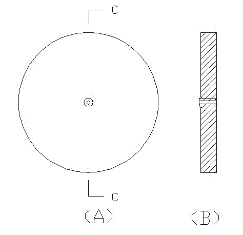
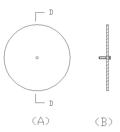
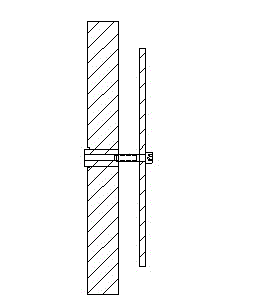
[0055] A manufacturing method of tooling for processing heat-treated deformed disc blades, taking the production and grinding of φ320×φ220×10LD type slitting machine disc blades as an example, the shape of the tooling used is as follows figure 1 , figure 2 and image 3 As shown, the manufacturing method includes the processing of the main body of the tooling and the processing of the accessories of the tooling, and the steps are:

[0056] A. Processing of tooling body

[0057] (1) Preparation of main raw materials for tooling:

[0058] The main body of the tooling is made of forged blank. The mass percentage of the forged blank components is: C: 0.95-1.05%, Mn: 0.25-0.45%, Si: 0.15-0.35%, S: ≤0.020%, P: ≤0.027% , Cr: 1.40-1.65%, and the balance is Fe; this range is acceptable, and the preferred mass percentages of the components of the tooling body forging blank in this embodiment are: C: 1.00%, Mn: 0.34%, Si: 0.23%, S : ≤0.020%, P: ≤0.027, Cr: 1.50%, and the balance is ...

Embodiment 2

[0082] Same as Example 1, the difference is that in step (1), the mass percentages of the processed forging blank components of the tooling body are: C: 0.95%, Mn: 0.45%, Si: 0.15%, S: ≤0.020%, P : ≤0.027%, Cr: 1.65%, and the balance is Fe; during the annealing treatment of the forged blank in step (2), the annealing temperature is 790°C, the annealing time is 6 hours, and it is cooled to 710°C in the annealing furnace. Air cooling; heat treatment of the tooling body in step (4): heating to 860°C in 18 minutes, and the temperatures of the two temperings are 150°C and 160°C respectively; the mass percentage of the forged blank components in step (7) is: C: 0.55%, Si: 0.37%, Mn: 0.50%, P: ≤0.035%, S: ≤0.040%, Cr: 0.20%, Cu: 0.20%, the balance is Fe; the annealing temperature in step (8) is 770°C , the annealing time is 5 hours, and air cooling is performed after cooling to 680°C in the annealing furnace. The main body of the tooling and the accessories of the tooling are fasten...

Embodiment 3

[0084] Same as Example 1, the difference is that in step (1), the mass percentages of the processed forging blank components of the tooling body are: C: 1.05%, Mn: 0.25%, Si: 0.35%, S: ≤0.020%, P : ≤0.027%, Cr: 1.40%, and the balance is Fe; during the annealing treatment of the forged blank in step (2), the annealing temperature is 810°C, the annealing time is 4 hours, and it is cooled to 720°C in the annealing furnace. Air cooling; heat treatment of the tooling body in step (4): heating to 860°C in 19 minutes, and the temperatures of the two temperings are 165°C and 165°C respectively; the mass percentage of the forged blank components in step (7) is: C: 0.65%, Si: 0.17%, Mn: 0.80%, P: ≤0.035%, S: ≤0.040%, Cr: 0.10%, Cu: 0.10%, Ni: 0.10%, and the balance is Fe; in step (8) The annealing temperature is 760°C, the annealing time is 6 hours, and air cooling is performed after cooling to 668°C in the annealing furnace. The main body of the tooling and the accessories of the tool...


PUM


Abstract

The invention discloses a manufacturing method for a tool for machining a heat treatment deformation circular-disc blade. The manufacturing method comprises machining of a tool main body and machining of a tool accessory and comprises the following steps: (1) preparing tool main body raw materials; (2) annealing a forged blank; (3) initially machining the forged blank into a tool main body; (4) carrying out heat treatment on the tool main body; (5) deeply machining the tool main body; (6) detecting the tool main body; (7) preparing tool accessory raw materials; (8) annealing a forged blank ofthe tool accessory; (9) turning of the forged blank of the tool accessory; and (10) tightening the tool main body and the tool accessory together by using a bolt for combined use. According to the invention, through reasonable ingredient composition and a heat treatment process corresponding to the ingredient, a deformation-free effect of the tool is achieved; and during fixing the circular-disc blade, a deformation layer of the circular-disc blade can be rapidly eliminated, so that the machining accuracy of the circular-disc blade is improved and the qualified rate of products is increased.

Description

technical field [0001] The invention relates to the technical field of tool processing, in particular to a method for processing a tool used in processing a disc blade of a slitting machine, and more specifically to a method for manufacturing a tool for processing a heat-treated deformed disc blade. Background technique [0002] The slitting and slitting machine relies on the disc blade of the slitting machine to roll on the plate to complete the infinitely long shearing action of the plate. The slitting and slitting machine is used for longitudinal rolling shearing of metal coils, aluminum plates, stainless steel plates, silicon steel plates, plastic sheets, PVC, paper, etc. Slitting machine disc blades are widely used in aerospace, automobile manufacturing, mining machinery, hardware manufacturing, home appliances, building materials, packaging, electric power and other industries. For example, Chinese Patent Application No. 201110183791.2, titled as a patent for a method...

Claims


Application Information

Patent Timeline
IPC IPC(8): B23P15/00C22C38/42C22C38/16C22C38/20C22C38/18C21D1/26C21D1/18
Inventor 张增明陈本真谢敏
Owner MAANSHAN HENGLIDA MACHINE BLADE
Why Eureka
Try Eureka