High wear-resistant valve pressurizing oil seal

A highly wear-resistant, valve technology, applied in lift valves, engine components, machines/engines, etc., can solve the problems of engine turbocharged sealing performance decline, aggravation of other parts loss, wear of sealing lip and other problems, so that it is not easy to wear , Eliminate potential safety hazards, ensure normal work and the effect of wear and tear

Inactive Publication Date: 2013-03-20
广东天诚密封件股份有限公司
View PDF6 Cites 4 Cited by
  • Summary
  • Abstract
  • Description
  • Claims
  • Application Information

AI Technical Summary

Problems solved by technology

[0002] With the rapid development of the automobile industry and the continuous innovation and application of science and technology, the core technology of the automobile is still the engine, and the performance of the engine depends on each component in the power system. The performance of the engine is brought out perfectly. Today's engine types are mainly divided into two types: naturally aspirated and turbocharged. However, the pressure of the turbocharged engine on the intake and exhaust is relatively high, and the current valve oil seal cannot fully meet the requirements. Use requirements, working at high speed and high pressure for a long time is easy to wear the sealing lip, which will reduce the sealing performance of the engine turbocharger, increase the loss of other parts, and pose a safety hazard

Method used


Image

  • High wear-resistant valve pressurizing oil seal
  • High wear-resistant valve pressurizing oil seal
  • High wear-resistant valve pressurizing oil seal

Examples


Embodiment Construction

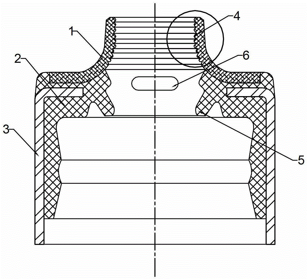
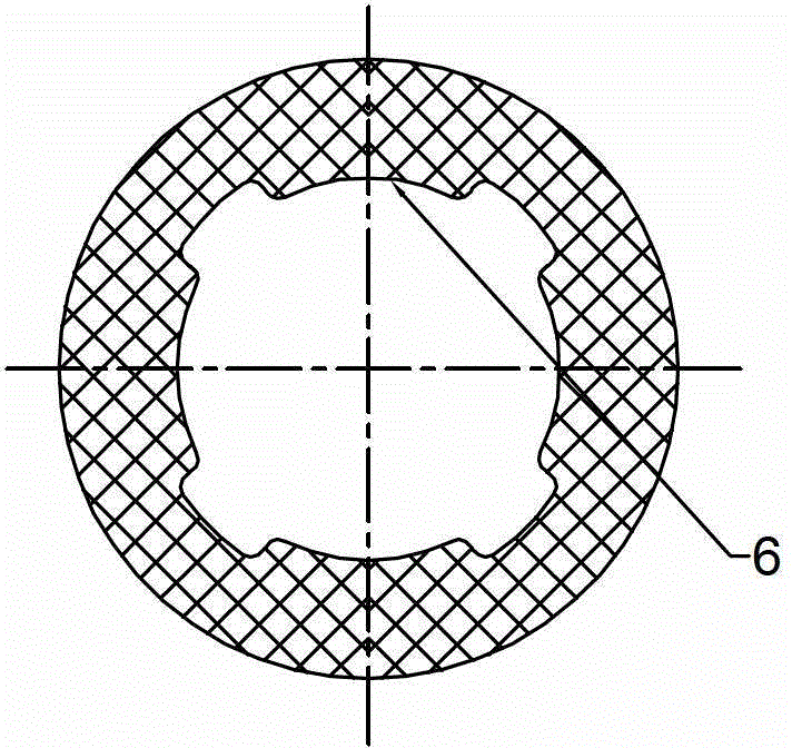
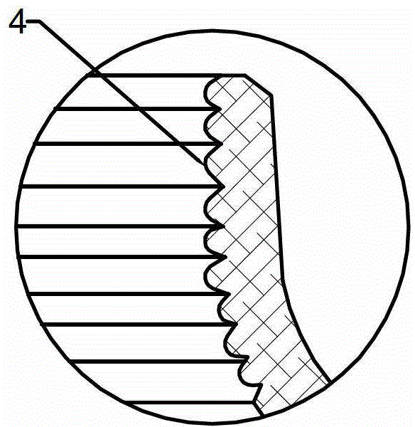
[0012] Such as figure 1 As shown, in this embodiment, the PTFE patch 1, the rubber body 2, and the skeleton 3 are vulcanized and bonded by a mold. After molding, a main lip 4 that is interference-fitted with the valve stem 8 is formed on the PTFE patch 1. The main lip 4 is in a ring-shaped sawtooth shape. On the rubber body 2, a back pressure air lip 5 with an interference fit with the valve stem 8 and 4 bosses 6 with a clearance fit with the valve stem 8 are formed. The bosses 6 are divided into 4 equal parts. Evenly distributed, the gap between the valve stem 8 is 0.1-0.2mm, the boss 6 is located between the back pressure air lip 5 and the main lip 4, and the distance between two adjacent bosses 6 is less than or equal to 1 / 2 The length of the boss 6.

[0013] Such as Figure 4 As shown, after the assembly of the present embodiment, the main lip 4 and the valve stem form 8 form a multi-lip interference fit. Since the main lip 4 is made of PTFE material, it has anti-wear ch...


PUM


Abstract

The invention disclose a high wear-resistant valve pressurizing oil seal of an engine. The oil seal comprises a rubber body, a framework and a PTFE (polytetrafluoroethylene) patch, and is shaped by vulcanization bonding by three different materials. After shaping, a main lip port which is in interference fit with a valve rod is generated on the PTFE patch; the lip port of the PTFE patch is in a circular jagged shape; and a pressure-bearing air lip which is in interference fit with the valve rod is generated on the rubber body. Four convex plates which are annularly distributed are arranged on the rubber body 2; and the surface of the convex plate is in clearance fit with the valve rod. Because the PTFE patch has a circular jagged multi-lip port structure, the PTFE patch can be used under high-speed and high-pressure working condition for a long time and is difficult to wear; the pressure-bearing air lip is arranged at the lower part of the lip port of the PTFE patch, the oil leakage amount of the engine can be effectively prevented from entering a cylinder under a turbo charging condition, and the cylinder is prevented from carbon deposition; and four convex plates which are annularly distributed are arranged from the lip port of the PTFE patch to the middle part of the pressure-bearing air lip, when the valve rod works, the valve rod has auxiliary guiding and protection functions, and the service life is prolonged.

Description

technical field [0001] The invention relates to a turbocharging valve oil seal, in particular to a highly wear-resistant valve supercharging oil seal. Background technique [0002] With the rapid development of the automobile industry and the continuous innovation and application of science and technology, the core technology of the automobile is still the engine, and the performance of the engine depends on each component in the power system. The performance of the engine is brought out perfectly. Today's engine types are mainly divided into two types: naturally aspirated and turbocharged. However, the pressure of the turbocharged engine on the intake and exhaust is relatively high, and the current valve oil seal cannot fully meet the requirements. Due to the requirements of use, working under high speed and high pressure for a long time is easy to wear the sealing lip, which will reduce the sealing performance of the engine turbocharger and increase the loss of other parts...

Claims


Application Information

Patent Timeline
Patent Type & Authority Applications(China)
IPC IPC(8): F01L3/08
Inventor 吴克胜陈庆斌何洪
Owner 广东天诚密封件股份有限公司
Why Eureka
Try Eureka