Energy collection unit and ratchet wheel and a wave force engine

A technology of energy harvesting and ratcheting, which is applied to engine components, machines/engines, and ocean energy power generation. It can solve problems such as poor adaptability to the operating environment, long construction period, and many energy conversion links, and achieve low production and operating costs. The effect of simple and fast maintenance and less conversion links

Active Publication Date: 2013-03-20
刘运桃
View PDF9 Cites 8 Cited by
  • Summary
  • Abstract
  • Description
  • Claims
  • Application Information

AI Technical Summary

Problems solved by technology

[0014] 1 Technical problems: Looking at the wave energy devices that have been tested and applied, there are mainly the following technical problems that need to be solved, such as complex structure, high manufacturing cost, difficult on-site construction, long construction period, affected by terrain, geology, sea conditions, The impact of tidal range is large, the ener

Method used


Image

  • Energy collection unit and ratchet wheel and a wave force engine
  • Energy collection unit and ratchet wheel and a wave force engine
  • Energy collection unit and ratchet wheel and a wave force engine

Examples


Embodiment 1

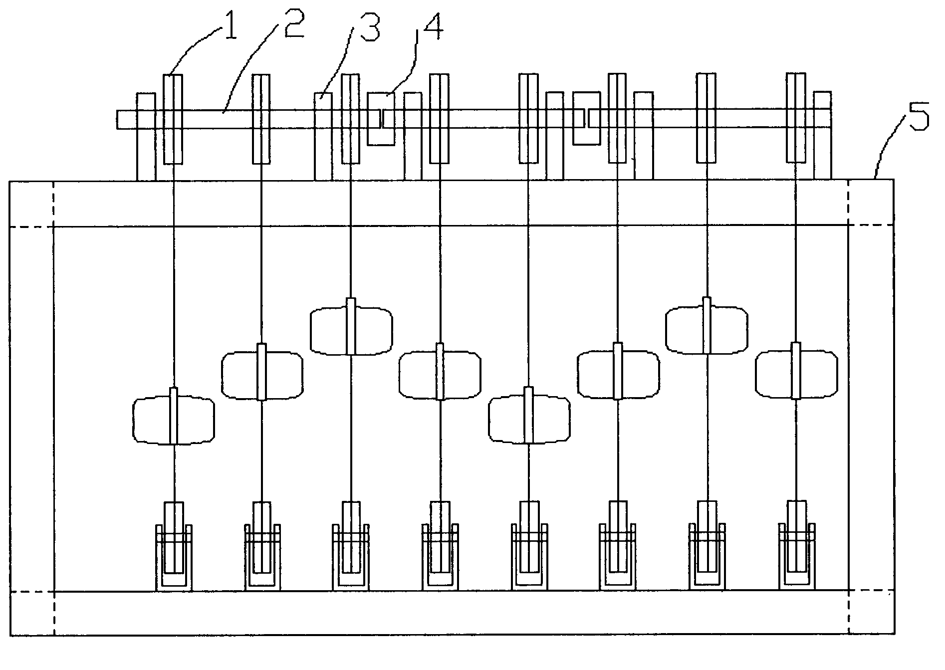
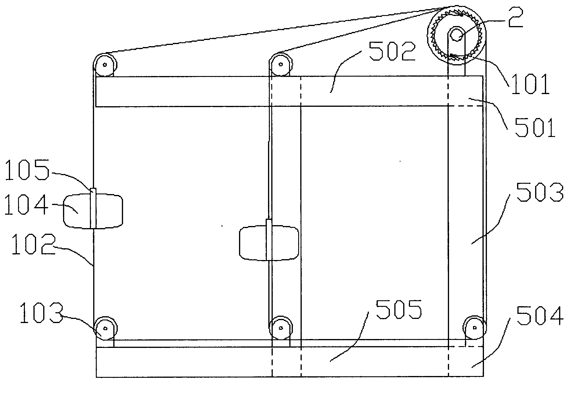
[0044] Example 1: see figure 1 A wave power engine of the present invention is composed of a frame 5, a synchronizing shaft 2, a bearing seat 3, and an energy harvesting unit 1, and the synchronizing shaft 2 is also a power output shaft; figure 2 It is shown that the frame 5 includes an upper platform composed of an upper longitudinal beam 501 and an upper transverse beam 502, a lower platform composed of a column 503, a lower longitudinal beam 504 and a lower transverse beam 505. The frame 5 is prefabricated with reinforced concrete, or can be Manufactured from metal materials (such as steel) or plastic-steel composite materials or other materials, prefabricated or integrated in the workshop, and fixedly installed in rivers, lakes or oceans rich in wave energy through pile platforms (pile foundation platforms), the frame height is 5 and the piles The height of the platform is determined according to the maximum wave height and maximum tidal range of the location. It should b...

Embodiment 2

[0045] Embodiment 2: This example has the same frame 5, synchronizing shaft 2, bearing seat 3 as in Embodiment 1, and the synchronizing shaft 2 is also the structure and arrangement of the power take-off shaft, as well as descriptions. In order to save space, the description will not be repeated here. The difference lies in the energy harvesting unit 1, strictly speaking, only in the ratchet device 101; see Figure 7 , Figure 8 , Figure 9 , Figure 10 , it is more preferable to use an energy storage ratchet, the energy storage ratchet includes ratchet wheels 101a, 101f, a ratchet wheel seat 101b, a pawl 101c, springs 101d, 101e, bearings 101h, 101g, the ratchet wheel seat 101b is installed with two identical The ratchet wheels 101a and 101f are oriented in the opposite direction, and one or more pawls 101c are used to limit the rotation of the ratchet wheel seat 101b in only one direction. The mainspring) transmits power to the synchronizing shaft 2, and is installed on t...

Embodiment 3

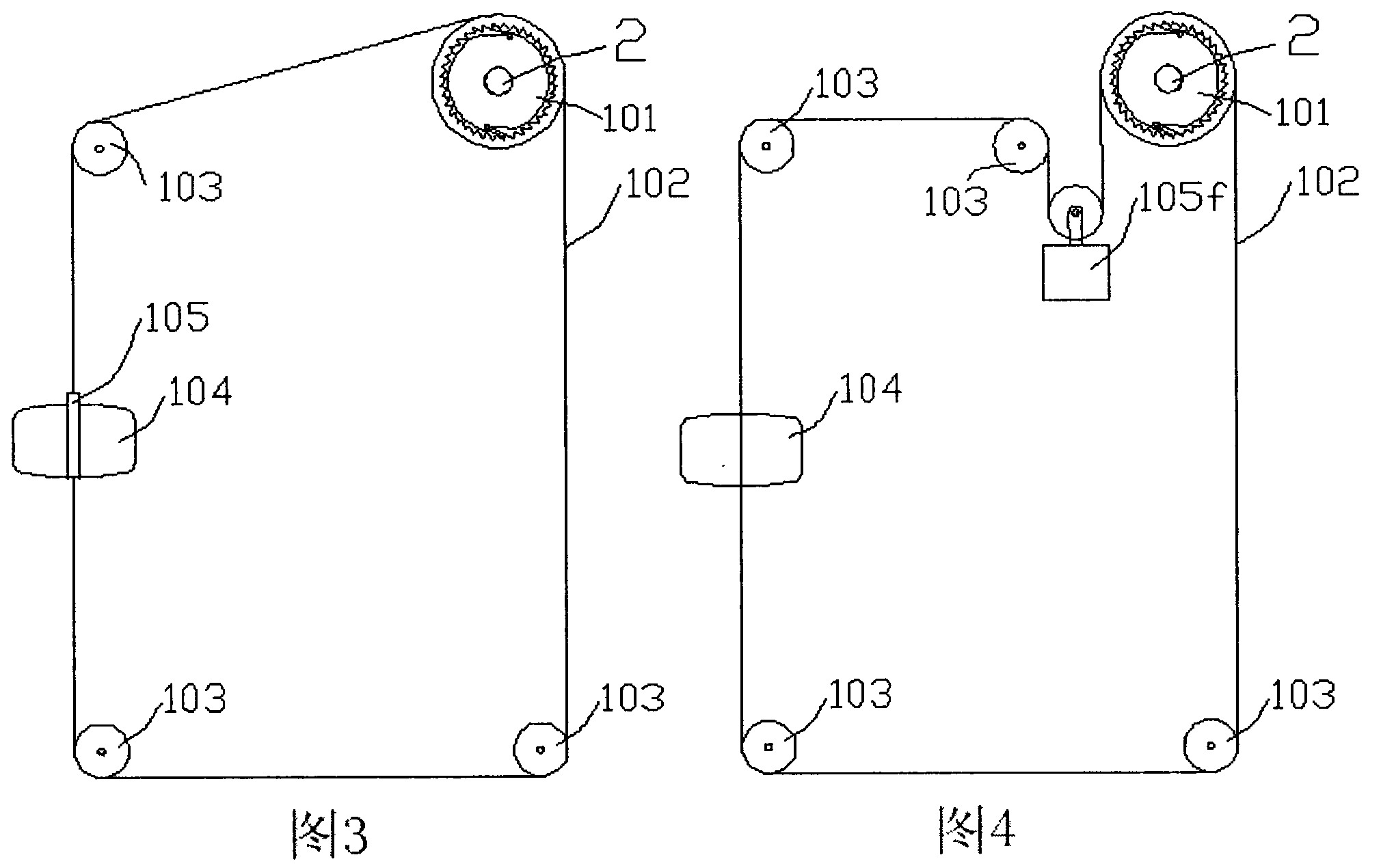
[0046] Embodiment 3: This embodiment has the same frame 5, synchronizing shaft 2, bearing seat 3 as Embodiment 1 or Embodiment 2, and the synchronizing shaft 2 is also a power output shaft and other structures, layouts and descriptions. To save space, they are omitted here. To repeat the description again, the difference lies in the energy harvesting unit 1, and the emphasis lies in the difference in the preloading device 105; see Figure 4 , in this example, the energy harvesting unit 1 is composed of a ratchet device 101, a pulley 103, a float 104, a transmission chain, and a heavy hammer device 105f. Suspending a group of heavy weight blocks on the transmission chain between them through the pulley 103 can also play the same effect as the preload spring, and can have a larger working distance; one end of the transmission chain is fixed at the lower part of the float 104, and the other end is wound around. Over the pulley 103, the weight between the pulley 103 and the ratche...


PUM


Abstract

The invention provides an energy collection unit and a ratchet wheel and a wave force engine. The energy collection unit and the ratchet wheel and the wave force engine are used for collecting and gathering low-speed unordered and intermittent mechanical energy to form mechanical energy which is powerful, stable and continuous in output. The energy collection unit and the ratchet wheel and the wave force engine are particularly suitable for wave energy of rivers, lakes and oceans. The energy collection unit and the ratchet wheel and the wave force engine comprise a frame, a synchronous shaft, bearing seats, and an energy collection unit. The synchronous shaft is installed on the upper portion or the lower portion of the frame through the bearing seats. The synchronous shaft is namely a power output shaft. At least one set of the energy collection unit is installed on the synchronous shaft. Flexible transmission parts of the energy collection unit form a closed polygon force transmission structure through pulleys, floaters, pre-tensioners, and a ratchet wheel device, wherein the pulleys are installed on the lower portion and the upper portion of the frame, and the ratchet wheel device is installed on the synchronous shaft. The development of wave energy is renewable energy utilization which is green, clean and environmental friendly, material resources are not consumed, no emission or waste is produced, affects of wave sizes and tidal levels are overcome, and meanwhile, the collected standing wave energy, traveling wave energy and tidal energy can be used for power generating, sea water desalination, hydrogen generation, mechanical energy required for various processing methods, and the like.

Description

technical field [0001] The invention belongs to the technical field of wave energy utilization, and in particular relates to an energy harvesting unit, a ratchet wheel and a wave power engine. Background technique [0002] With the progress of society and the rapid development of the economy, the demand for energy is increasing day by day, resulting in the depletion of fossil energy including oil, coal, natural gas, and the environmental problems caused by the excessive use of these energy sources. Solving the problems of energy crisis and environmental pollution has become the two major themes of today's society, and exploring clean and renewable energy is the only way to achieve sustainable development. In fact, energy is everywhere, the sunshine, the cold wind, the roaring sea, these are the treasure houses of our energy. How to develop these resources efficiently and at low cost is a major issue that needs to be solved urgently. [0003] Among them, the research of oce...

Claims


Application Information

Patent Timeline
IPC IPC(8): F03B13/16F16H33/02
CPCY02E10/38Y02A20/144Y02E10/30
Inventor 刘运桃
Owner 刘运桃
Why Eureka
Try Eureka