
Small size planar antenna with five frequency ranges being covered

A planar antenna, small size technology, applied to antennas, resonant antennas, antenna grounding devices, etc., can solve the problems of small isolation distance of the antenna, increase the difficulty of antenna design, etc., achieve a wide working bandwidth, suppress the current distribution on the metal ground surface, reduce damage effect

Inactive Publication Date: 2013-03-20
UNIV OF ELECTRONIC SCI & TECH OF CHINA
View PDF7 Cites 15 Cited by
  • Summary
  • Abstract
  • Description
  • Claims
  • Application Information

AI Technical Summary

Problems solved by technology

[0004] At present, the main difficulty in designing mobile phone antennas is: how to design a mobile phone antenna with small size, low profile, multi-band broadband operation, low cost and easy processing in a given environment
In order to meet the multi-function requirements, the current mainstream mobile phones generally set various data transmission ports on the edge of the antenna, thereby reserving a very small isolation distance for the antenna design and increasing the difficulty of antenna design.

Method used


Image

  • Small size planar antenna with five frequency ranges being covered
  • Small size planar antenna with five frequency ranges being covered
  • Small size planar antenna with five frequency ranges being covered

Examples


Embodiment Construction

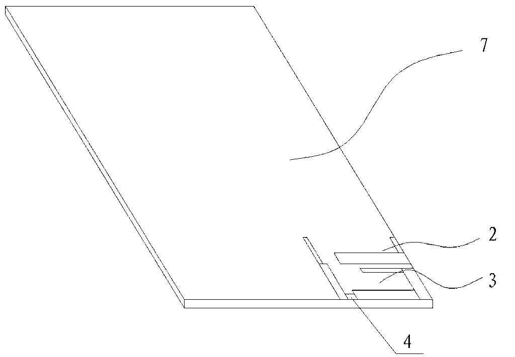
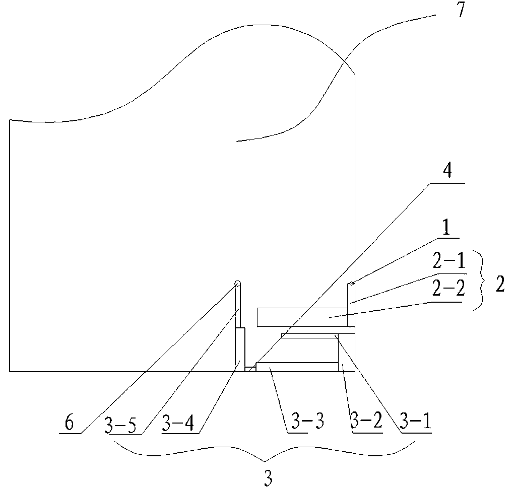
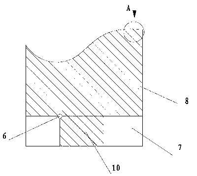
[0019] see Figure 1~Figure 4 , the antenna system of the present invention includes a dielectric plate 7, an antenna unit 3 positioned on the upper surface of the dielectric plate 7, and a main metal ground plate 8 disposed on the lower surface of the dielectric plate 7, and also includes a ground plate arranged on the lower surface of the dielectric plate 7, and The extended metal ground plate 10 connected to the main metal ground plate 8 and adjacent to the opposite area of ​​the antenna unit; the antenna unit includes the L-shaped high-frequency radiation unit 2 connected to the feed end and the L-shaped high-frequency radiation One side of the unit 2 is coupled and fed, and a bent and turned low-frequency radiation unit 3 is provided with a lumped chip inductor 4. The terminal of the bent and turned low-frequency radiation unit 3 is connected to the main metal ground plate 8 by means of a metallized through hole 6 connect. The expanded metal ground plate 10 realizes two...


PUM

PropertyMeasurementUnit
Inductance valueaaaaaaaaaa

Abstract

The invention discloses a small size planar antenna with five frequency ranges being covered. The small size planar antenna with the five frequency ranges being covered structurally comprises a dielectric plate and a main metal earth plate, wherein the dielectric plate is provided with an antenna element in a positioning mode, and the main metal earth plate is arranged on the lower surface of the dielectric plate. The antenna element is of a planar composite structure, and comprises an L-shaped high frequency radiation unit and a bent rotary type low frequency radiation unit, wherein the L-shaped high frequency radiation unit is connected with a feed end, the bent rotary type low frequency radiation unit is coupled to the L-shaped high frequency radiation unit in a feeding mode and is provided with a lumped chip inductor, and the terminal of the bent rotary type low frequency radiation unit is connected with the main metal earth plate by the aid of a metallizing through hole. According to the small size planar antenna with the five frequency ranges being covered, a terminal antenna is small in occupied space and merely occupies one corner of a mobile phone mainboard, saved space can be reserved as a blank metal-free copper-coated substrate so that space is supplied for other antenna designs, and thus the small size planar antenna with the five frequency ranges being covered is applied to the existing multiple-input-multiple-output (MIMO) system. By the aid of the small size planar antenna with the five frequency ranges being covered, an expansion metal earth plate is increased, electromagnetic wave radiation to a human body is reduced, and moreover, the area can be provided with other connector elements in a matching mode, and thereby the size of the antenna is effectively decreased.

Description

technical field [0001] The invention belongs to the field of electromagnetic field and microwave technology, and specifically relates to the field of antenna technology, especially a small-sized planar antenna covering five frequency bands. Background technique [0002] With the rapid development of mobile communication technology and market in the 21st century, under the combined effect of new technology and market demand, the future mobile communication technology will present the following major trends: network business data, packetization, mobile Internet gradually formed; network technology Digitization and broadband; intelligentization and miniaturization of network equipment; application to higher frequency bands and effective use of frequency; integration, globalization and personalization of mobile networks; integration of various networks; high speed, high quality and low cost . This is the direction and goal of the development of the third generation (3G)...

Claims


Application Information

Patent Timeline
IPC IPC(8): H01Q1/38H01Q1/48H01Q5/01H01Q9/04H01Q5/10
Inventor 杨顺班永灵李乐伟李鹏鹏王朗
Owner UNIV OF ELECTRONIC SCI & TECH OF CHINA
Learn More