Method for manufacturing golf club head

A golf club head and manufacturing method technology, applied to golf balls, golf clubs, rackets, etc., can solve the problems of difficult dimensional precision control, wear and tear, increased manufacturing costs, etc., to save processing operations and costs, and reduce wear and tear rate effect

Inactive Publication Date: 2013-03-27
黄荣贤
View PDF6 Cites 8 Cited by
  • Summary
  • Abstract
  • Description
  • Claims
  • Application Information

AI Technical Summary

Problems solved by technology

[0003] The production of the first heavy club head of golf clubs, the production of existing golf club heads, is mainly based on casting and forging methods, and in the forging method, hot forging is the main method of implementation. Existing hot forging golf clubs For the method of making the head, see figure 1 , figure 2 , is the constant temperature forging method of golf head in China Taiwan Announcement No. I270421, which includes the steps of: (1) providing blanking material 10, taking a pre-forging material 14 made of metal; (2) providing constant temperature forging molding 11, the pre-forging The forging material 14 is forged under the same conditions as the heating temperature of the molding die (not shown in the figure), and the preferred temperature is between 600 and 1000°C; Forgings 15 are trimmed on the profile; and (4) surface treatment 13 is provided to complete the method of forging finished forgings 16; however, in view of the forging process of the aforementioned manufacturing method, the pre-forged material 14 and the mold are kept in a certain high-temperature environment for forging , not only consumes energy costs such as electric energy, but also the material 14 is prone to thermal expansion and contraction problems under high-temperature forging, so that it is difficult to control the dimensional precision; moreover, because the existing golf club head forming mold adopts an open mold, in order to target The material 14 is forged as a whole, and the pressurized load is large, which is a great loss to the forging mold. In addition, after forging, the forging 15 will squeeze out the remaining material 151 into the gap between the molds, so another process is often required after forging. Repair and remove surplus material 151 procedures, resulting in improper loss of materials and increased manufacturing costs
[0004] refer to image 3 , there is another method of forging a golf club head by forging, which is the forging blank of a golf club head announced in Taiwan, China No. I236941, which uses a casting method to make a material 20 into a blank 21, the blank 21 is provided with a preset bending portion 211, and the two ends of the preset bending portion 211 are respectively connected with a rod head 212 and a set of handle 213, and at least one forging die 22a, 22b is used for the blank 21. After forging and pressing, demoulding and cooling and setting, the forging burr 24 formed in the cavity 23 of the forging die 22b is cut off, and the surface processing 25 is carried out according to the situation, and finally a rod head product 26 is formed; however, this The prior art still has imperfections, because the prior art mainly utilizes a dewaxing casting method to manufacture the embryo 21, and the dewaxing casting needs to be completed under heating operation, that is, using wax liquid perfusion, wax mold Only when the procedures such as dipping and melting can be completed, it is inevitable that slag holes will be generated on the surface of the embryo 21 and the density will be uneven, so that the quality of the finished club head 26 after subsequent forging is not good; moreover, the forging dies 22a, 22b still need to Forging the whole blank 21, the large stamping area will increase the load bearing force of the forging dies 22a, 22b, which will easily lead to wear and tear of the forging dies 22a, 22b. In addition, the whole process needs to be heated, which still consumes energy costs and precise dimensions. In addition, the degree of control is not easy, and the operation of trimming and removing the burrs 24 is still required after forging, resulting in an increase in manufacturing costs

Method used


Image

  • Method for manufacturing golf club head
  • Method for manufacturing golf club head
  • Method for manufacturing golf club head

Examples


Embodiment Construction

[0030] In order to further explain the technical solution of the present invention, the present invention will be described in detail below through specific examples.

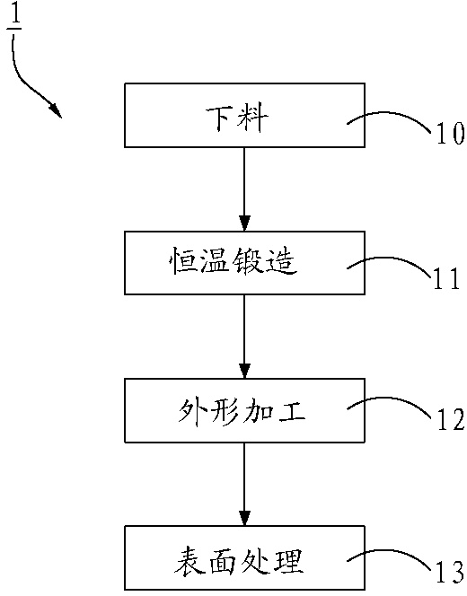
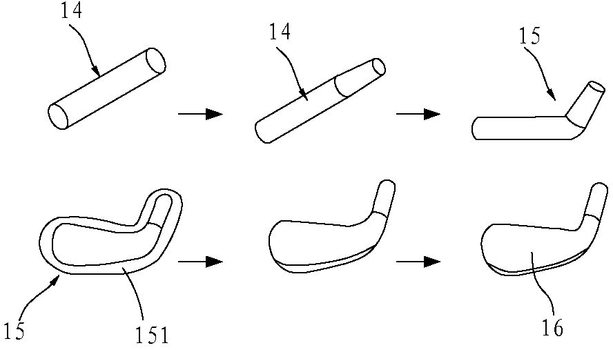
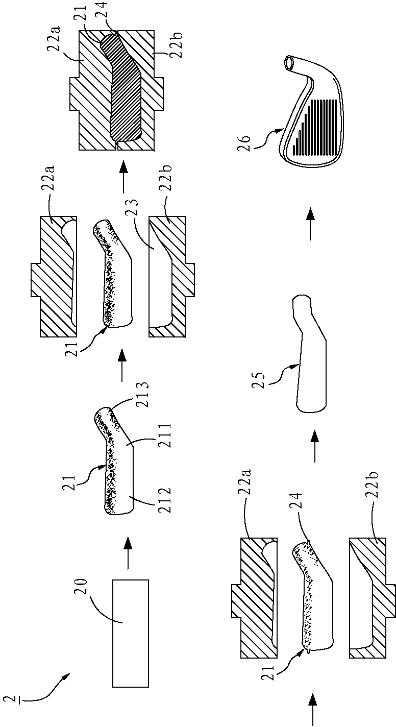
[0031] refer to Figure 4 , a preferred embodiment of the golf club head manufacturing method 3 of the present invention, which sequentially includes a cutting step 31, a bending forming step 32, and a forging step 33; wherein, in the cutting step 31, it is prepared in advance Place a base material 5, utilize a punching die (not shown in the figure) to be cut into shape according to required size, and in the present embodiment, the width of the two ends 5a, 5b of this base material 5 gained after cutting can be To be different, and to match the size of a golf club body (not shown), one end 5a of the base material 5 can be tapered, as shown in the figure, so that the base material 5 The widths of the two ends 5b, 5a are large and small; moreover, in the bending and forming step 32, the base material 5 is bent a...


PUM


Abstract

The invention relates to a method for manufacturing a golf club head. The method sequentially comprises the following steps of: cutting, bending and forming, and forging. The method mainly comprises the steps of: taking a cut base material, bending and forming the base material to be separated into a supporting part and a forming part; repeatedly performing cold forging and stamping on the obtained forming part, and forming a shape of the golf club head. Therefore, only the forming part is required to be locally stamped in the forging process, the loss rate of the forming die is reduced, any heating operation is not required in the whole process, the energy cost is saved, the formed golf club head is uniform in density, scraps of the base material in the forging process are avoided, and the operation and cost required to machine and remove the scraps after forging are saved.

Description

technical field [0001] The invention relates to a forging operation of a golf club head, in particular to a method for manufacturing a golf club head formed by cold forging, stamping and forging. Background technique [0002] With the evolution of the social atmosphere, people's living standards are improving day by day, and people begin to pay attention to leisure activities to adjust the pace of life. Golf is widely popular because of its skills, fun and the ease of walking as the venue changes. The hobbies of people of all ages; golf courses are organized by using natural terrain, such as mountain courses, woods courses, river courses and hill courses, etc., to show courses with different terrain styles, and people are immersed in the natural environment. It can be well relieved, and the changing court style also increases the challenge of sports. In order to overcome the challenge of the court terrain, in addition to relying on the player's own skills, it is also necessa...

Claims


Application Information

Patent Timeline
IPC IPC(8): A63B53/04A63B102/32
Inventor 黄荣贤
Owner 黄荣贤
Why Eureka
Try Eureka