Implementation method of selective laser sintering (SLS) technology and fiber implantation device

A technology of laser sintering and implementation method, which is applied in processing and manufacturing, additive processing, solid material additive processing, etc., can solve the problems of low strength impact strength, low strength, and low strength of molded parts, and achieve fiber aspect ratio Improvement, high-strength use requirements, and the effect of increasing strength

Inactive Publication Date: 2013-03-27
广州市锐鼎机电设备有限公司
5 Cites 30 Cited by

AI-Extracted Technical Summary

Problems solved by technology

After the powder material is laser sintered, the strength of the molded part is low. The main reason for the low strength is its loose texture and low density.
Although mixing glass fiber, glass microspheres, mineral fiber, carbon fiber and other reinforcing materials in the powder material can increase the strength of the molded part, the arrangement of these reinforcement materials in...

Method used

In the present embodiment, the fiber filaments 8 in the molded part 15 are embedded in its body in parallel orderly, so that the molded part 15 obtains the highest mechanical properties in the alignment direction of the fibers, and the fiber alignment direction pulls The tensile strength and modulus are the highest.
Referring to Fig. 1, Fig. 2 and Fig. 5, support and base 1 are connected by rotating joint, specifically, one end of support and the lower end of base 1 are connected by rotating shaft 3, so that the angle between suppor...

Abstract

The invention discloses an implementation method of a selective laser sintering (SLS) technology and a fiber implantation device. The implementation method comprises the following steps: when sintering, implanting fibrous layers which are composed of fibers with high length-diameter ratio and ordered arrangement into sintered powder, wherein after sintering, the fibrous layers are wrapped in the sintered molded piece, specifically, the fibrous layers can be formed by sequentially arranging fiber yarns or fiber bundles and the like in the sintered powder layers by virtue of the fiber implantation device or paving fiber clothes or fiber felts. According to the implementation method of selective laser sintering technology disclosed by the invention, every sintered layer is implanted with the fibrous layer composed of fibers with high length-diameter ratio and ordered arrangement, compared with the condition that short and unordered fibers are mixed in the sintered powder in the prior art, the method disclosed by the invention has the advantages that the length-diameter ratios of the fibers in the sintered layer are greatly increased, and the fibers are arranged in order, so that the strength of a molded piece is greatly improved, and thus the molded piece can meet the use requirement with higher strength.

Application Domain

Additive manufacturing apparatusAdditive manufacturing with solids

Technology Topic

Fibrous layerDiameter ratio +8

Image

  • Implementation method of selective laser sintering (SLS) technology and fiber implantation device
  • Implementation method of selective laser sintering (SLS) technology and fiber implantation device
  • Implementation method of selective laser sintering (SLS) technology and fiber implantation device

Examples

  • Experimental program(6)

Example Embodiment

[0043] Example 1
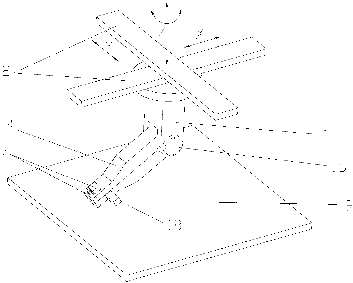
[0044] see figure 1 , the fiber implantation device of the present invention is mainly composed of a base 1 arranged on the slide rail 2 and a fiber conveyor 4 connected to the base 1, wherein,
[0045] see figure 1 , the slide rail 2 is a motion mechanism with four degrees of freedom, the four degrees of freedom are linear motion along the X-axis, Y-axis and Z-axis and rotation around the Z-axis, each motion is composed of a separate one Driven by stepper motors, these stepper motors are controlled by the control system, so that the base 1 connected with the slide rail 2 realizes the movement in the X-axis, Y-axis and Z-axis directions and rotation around the Z-axis; the specific embodiment can be Refer to the slide rail mechanism of the worktable in the CNC machining center.
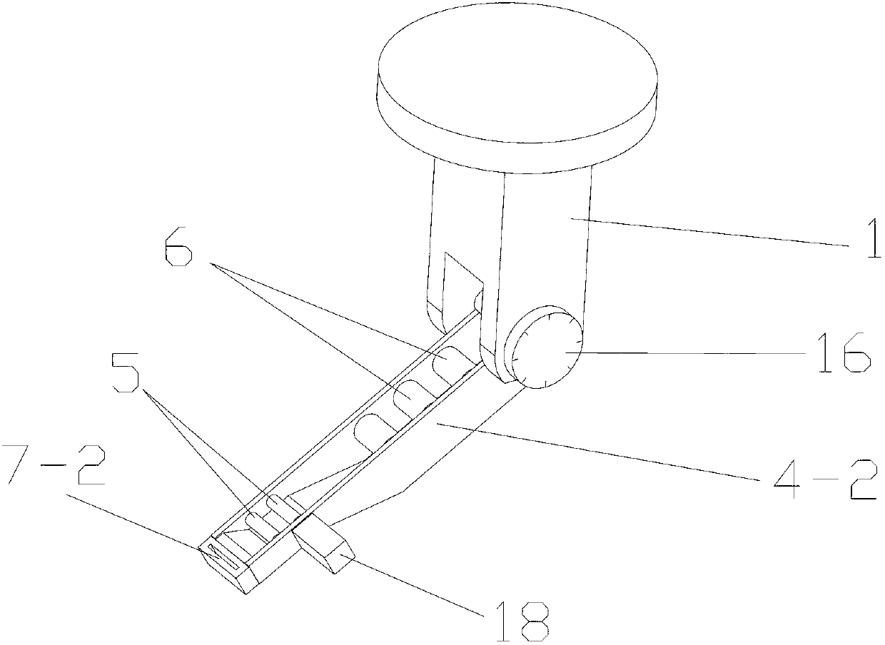
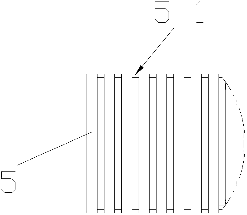
[0046] see Figures 1 to 7, the fiber conveyor 4 is mainly composed of a bracket, a traction roller group, an auxiliary roller group and a cutting mechanism 7, wherein the bracket is a shell composed of an upper shell 4-1 and a lower shell 4-2. A cavity is formed, the traction roller group and the auxiliary roller group are arranged in the cavity, and the cutting mechanism 7 is arranged at one end of the casing. The traction roller group is divided into two groups, each group is composed of two parallel traction rollers 5, one of which is arranged on the upper casing 4-1, the other is arranged on the lower casing 4-2, and the upper casing is When the body 4-1 and the lower shell 4-2 are combined, the two traction rollers 5 form a traction roller group; the auxiliary roller groups are three groups, each group is composed of two parallel auxiliary rollers 6, one of which is located in the On the upper shell 4-1, the other one is set on the lower shell 4-2. When the upper shell 4-1 and the lower shell 4-2 are combined, the two auxiliary rollers 6 form an auxiliary roller group; The wire 8 enters from one end of the casing, passes between the two auxiliary rolls 6 in the three sets of auxiliary rolls and between the two pulling rolls 5 in the two sets of pulling rolls, and finally extends from the other end of the shell. out. Among the two traction roller groups, the traction roller 5 connected to the lower casing 4-2 in the rear traction roller group is connected with a driving device, which is a stepping motor 18, and is located in the front traction roller group. The traction roller 5 connected with the lower casing 4-2 is connected with the traction roller 5 connected with the driving device through a belt, so that both sets of traction roller groups are driven by power. The function of the traction roller set is to transport the fiber filaments 8 clamped between the two traction rollers 5 forward through rotation. The gap between the two traction rollers 5 should be smaller than the diameter of the fiber filaments 8, but the traction roller 5 made of hard materials has the following disadvantages: if the diameter of the fiber filaments 8 changes, then the two traction rollers 5 need to be readjusted, and A gap adjustment mechanism is provided; in order to solve this problem, the traction rollers 5 can be made of elastic materials, such as rubber, so that the gap between the two traction rollers 5 can be set to zero, even if the surfaces of the two traction rollers 5 are slightly squeezed against each other Compression deformation, so that the fiber filaments 8 of various diameters pass through it, and the two pulling rollers 5 can effectively clamp the fiber filaments 8 without adjusting the gap; there is no driving device on the auxiliary roller set, and the In order to assist in positioning and guiding the conveying of the filaments 8 , the gap between the two auxiliary rollers 6 may be equal to or slightly larger than the diameter of the filaments 8 so as not to cause excessive resistance to the conveying of the filaments 8 . See Figures, 3 and Figure 4 , in order to provide better positioning and guiding effect for the transportation of fiber filaments 8, the surfaces of the traction roller 5 and the auxiliary roller 6 are respectively provided with circumferential guide grooves 5-1 and 6-1, two traction rollers 5 or two The guide grooves 5-1 or 6-1 between the auxiliary rollers 6 are combined together to form a guide channel through which the fiber filaments 8 pass; usually, the fiber conveyor 4 will convey several fiber filaments 8 at the same time. By arranging a plurality of parallel guide grooves 5-1 or 6-1, each guide groove 5-1 or 6-1 corresponds to one fiber filament 8, so that there is no interference between the multiple fiber filaments 8, and the order can be sent out. The stepping motor 18 on the pulling roller 5 is connected with the control system, and the conveying speed of the fiber filaments 8 can be adjusted by adjusting the rotation speed of the stepping motor 18 .
[0047] see Figure 5 to Figure 7 , the cutting mechanism 7 is arranged on the output end of the fiber filament 8 on the casing, and includes a knife seat, a cutting knife 7-4 and a driving mechanism, wherein the knife seat is connected to the end of the upper shell 4-1 by the upper knife The seat 7-1 is combined with the lower knife seat 7-2 connected to the end of the lower casing 4-2. A gap is formed between the upper knife seat 7-1 and the lower knife seat 7-2, and the fiber filaments 8 are formed by the gap. pass through. The opposite surfaces of the upper knife seat 7-1 and the lower knife seat 7-2 are respectively provided with inwardly recessed grooves 7-5, wherein the cutting knife 7-4 is arranged in the concave groove of the upper knife seat 7-1. In the groove 7-5, the cutter 7-4 is composed of a cutter body 7-6 and a cutter head 7-7. The cutting edge of the cutter body 7-6 faces the groove 7-5 of the lower cutter seat 7-2, The middle of the upper knife seat 7-1 is provided with a through hole 7-3 extending upward to the top surface of the upper knife seat 7-1, and the cutter head 7-7 of the cutting knife 7-4 protrudes from the through hole 7-3 to the upper knife The upper end face of seat 7-1. The driving mechanism is composed of a tension spring 10 and a driving device, wherein the tension spring 7-10 is arranged between the top of the knife body 7-6 and the upper knife seat 7-1, and the tension spring 7-10 is pulled under normal conditions. The cutting knife 7-4, so that the cutting edge of the cutting knife 7-4 is located in the groove 7-5 of the upper knife seat 7-1; the driving device is used to drive the cutting knife 7-4 to move downward, and the 8 for cutting, the driving device is composed of a driving motor 7-8 and a cam 7-9, wherein the cam 7-9 is in contact with the top surface of the cutter head 7-7 of the cutter 7-4, and the driving motor 7-8 is connected with the control When the system is connected, when working, the drive motor 7-8 drives the cam 7-9 to rotate. When the highest point of the cam 7-9 contacts the top surface of the cutter head 7-7, the blade of the cutter 7-4 is pushed down and cut into the lower knife The groove 7-5 of the seat 7-2, thereby cutting the filaments 8, and then the cutter 7-4 automatically resets under the action of the tension spring 7-10. Under the condition that the speed at which the fiber conveyor 4 conveys the fiber filaments 8 is determined, the length of the cut fiber filaments 8 can be controlled by controlling the frequency of cutting the fiber filaments 8 by the cutter 7-4.
[0048] see figure 1 , figure 2 and Figure 5 , the bracket and the base 1 are connected by a rotating joint. Specifically, one end of the bracket is connected with the lower end of the base 1 through the rotating shaft 3, so that the angle between the bracket and the base 1 can be adjusted, that is, the bracket and the sintering working plane can be adjusted. 9, so as to meet the technological requirements of inserting the fiber filaments 8 into the sintered powder material layer according to different inclination angles. In this embodiment, the adjustment of the angle between the bracket and the base 1 is manually realized by a knob 16, and a scale is provided between the knob 16 and the surface of the base 1, so that the angle can be adjusted accurately.

Example Embodiment

[0049] see Figure 8 , Figure 9 and Figure 10 , the implementation method of the selective laser sintering process of the present invention comprises the following steps:
[0050] (1) The working cylinder 11 descends a certain distance, the powder supply cylinder 12 rises a certain distance, and the powder spreading device 13 spreads a single layer or multiple layers of sintered powder material 14 on the sintering working plane 9 to form the bottom sintered powder material layer 14-1 ;
[0051] (2) Using a fiber implantation device to lay a fiber layer on the bottom sintered powder material layer 14-1, the laying process is:
[0052] (2.1) Under the control of the control system, the slide rail 2 in the fiber implantation device moves the fiber conveyor 4 to the target position; the fiber conveyor 4 simultaneously outputs a plurality of continuous long fiber filaments 8 in parallel, and the fiber conveyor 4 outputs the fiber filaments in parallel. 8 at the same time, the fiber conveyor 4 retreats backward, so that the output fiber filaments 8 can be laid flat in the bottom sintered powder material layer 14-1;
[0053] (2.2) Under the control of the control system, the cutting mechanism 7 in the fiber implantation device cuts the fiber filaments 8 according to the required length. Specifically, the control system cuts the fiber by controlling the control cutter 7-4 in the cutting mechanism 7 The frequency of the filament 8 controls the length of the fiber filament 8 being cut;
[0054] (2.3) The fiber implantation device continuously repeats the above steps (2.1) and (2.2), and lays the fiber filaments 8 on the bottom sintered powder material layer 14-1 in an orderly manner, and finally forms a fiber layer, specifically: a fiber conveyor 4. After completing the transportation and cutting of the fiber filaments 8 once, the slide rail 2 drives the fiber conveyor 4 to translate to the next target position, and the fiber conveyor 4 outputs a plurality of fiber filaments 8 to the bottom sintered powder material layer 14-1. and cut, and circulate in this way, and finally the bottom sintered powder material layer 14-1 is covered with fiber filaments 8 arranged in parallel and orderly to form a fiber layer;
[0055] (3) The working cylinder 11 is lowered for a certain distance, the powder supply cylinder 12 is raised for a certain distance, and the powder spreading device 13 spreads a single layer or multiple layers of sintered powder material 14 on the bottom sintered powder material layer 14-1 to form a covering fiber layer. The top layer of sintered powder material layer 14-2;
[0056] (4) The bottom sintered powder material layer 14-1 and the top sintered powder material layer 14-2 are sintered by the laser beam 10 emitted by the laser device 19. During sintering, the laser beam 10 only irradiates the sintered powder material 14 and the molded part. 15 For the parts corresponding to the main body, the rest of the parts are not sintered and are still in powder form; after sintering, the fiber layer is wrapped in the bottom sintered powder material layer 14-1 and the top sintered powder material layer 14-2 to complete the sintering of one sintered layer 20 Work;
[0057] (5) Repeat the above steps (1) to (4) continuously. During this process, the computer program determines whether all the sintered layers 20 of the molded part 15 have been sintered according to the instructions. If so, the sintering work of the molded part 15 is completed. If not, the execution is repeated until the sintering work of the molded part 15 is completed.
[0058] In this embodiment, the fiber filaments 8 in the molded part 15 are embedded in the body in parallel and orderly, so that the molded part 15 can obtain the highest mechanical properties in the fiber arrangement direction, and the tensile strength and The tensile modulus is the largest.
[0059] In this embodiment, the materials of the fibers in the fiber layer may be glass fibers, carbon fibers, nylon fibers, aramid fibers, spandex fibers, metal fibers, and the like.

Example Embodiment

[0060] Example 2
[0061] see Figure 9 In this embodiment, two sets of fiber implantation devices are used, and the fiber conveyors 4 in the two sets of fiber implantation devices are arranged obliquely opposite to each other, and the fiber filaments 8 output by the two sets cross each other. In the two fiber implantation devices, an angle adjustment motor 17 is provided at the connection joint between the bracket in the fiber conveyor 4 and the base 1, and the angle adjustment motor 17 is a stepper motor controlled by the control system, so as to realize the Automatic adjustment of the tilt angle of the stand. The other embodiments of the fiber implantation device of this example are the same as those of Example 1.
[0062] see Figure 9 and Figure 10 , the implementation method of the selective laser sintering process in this embodiment is realized by using the above-mentioned two sets of fiber implantation devices, and the difference from the implementation method in Embodiment 1 is:
[0063] In step (2.1), the two fiber conveyors 4 are fixed in one position and simultaneously output a plurality of continuous long fiber filaments 8 in parallel, and one end of the output fiber filaments 8 is inserted into the bottom sintered powder material layer 14-1, The other end protrudes out of the bottom sintered powder material layer 14-1, and the fiber filaments 8 output by the two fiber conveyors 4 cross each other.
[0064] In step (2.3), finally, on the bottom sintered powder material layer 14-1, a fiber layer that is laid across each other in a mesh shape is formed. One end of the fiber layer is inserted into the bottom sintered powder material layer 14-1, and the other end protrudes from the bottom layer. The sintered powder material layer 14-1 is outside.
[0065] In this embodiment, the fiber filaments 8 in the molded part 15 cross each other into a net shape and are embedded in the body in an orderly manner. Compared with the embodiment 1, the embodiment 2 makes the molded part 15 have a relatively high quality. Good overall performance, that is, the mechanical properties in different directions are relatively balanced.
[0066] For other implementations of the implementation method of this embodiment, reference may be made to Embodiment 1.

PUM

no PUM

Description & Claims & Application Information

We can also present the details of the Description, Claims and Application information to help users get a comprehensive understanding of the technical details of the patent, such as background art, summary of invention, brief description of drawings, description of embodiments, and other original content. On the other hand, users can also determine the specific scope of protection of the technology through the list of claims; as well as understand the changes in the life cycle of the technology with the presentation of the patent timeline. Login to view more.

Similar technology patents

Fibre compound temporary plugging agent

Owner:CHENGDU LEARN PRACTICES TECH CO LTD

Classification and recommendation of technical efficacy words

Why Eureka
Try Eureka