Exhaust gas decomposer of hydrogen peroxide plasma sterilizer

A plasma and hydrogen peroxide technology, applied in chemical instruments and methods, separation methods, dispersed particle separation, etc., can solve the problems of polluting the environment, rising, and threatening the health of equipment operators, and achieve the effect of decomposition and purification

Active Publication Date: 2013-04-03
LAOKEN MEDICAL TECH
View PDF3 Cites 3 Cited by
  • Summary
  • Abstract
  • Description
  • Claims
  • Application Information

AI Technical Summary

Problems solved by technology

[0002] In the medical field, the disinfection and sterilization of medical devices is particularly important. The sterilization methods are generally divided into high temperature and low temperature. The method of low-temperature disinfection and sterilization of medical instruments is hydrogen peroxide low-temperature plasma sterilization. The specific method is to place the medical instruments to be sterilized in the sterilization chamber of hydrogen peroxide low-temperature plasma sterilization equipment, and In the low-pressure environment similar to vacuum in the warehouse, the hydrogen peroxide is vaporized and plasmaized at low temperature, so as to sterilize the medical devices placed in it. During the sterilization process, it is necessary to use a vacuum pump several times to sterilize. The gas in the bacteria chamber is sucked to reduce the air pressure in the sterilization chamber, so that the hydrogen peroxide liquid is vaporized at a low temperature, and a vacuum pump is required to suck the hydrogen peroxide gas into the sterilization chamber and pipeline medical equipment The inner cavity of the sterilizer realizes low-temperature sterilization. After the sterilization is completed, a vacuum pump is needed to extract the waste gas in the sterilization chamber. The air or hydrogen peroxide waste gas is pumped away, and the pumped gas is first pumped into the vacuum pump by the vacuum pump, and t

Method used


Image

  • Exhaust gas decomposer of hydrogen peroxide plasma sterilizer
  • Exhaust gas decomposer of hydrogen peroxide plasma sterilizer
  • Exhaust gas decomposer of hydrogen peroxide plasma sterilizer

Examples


Embodiment Construction

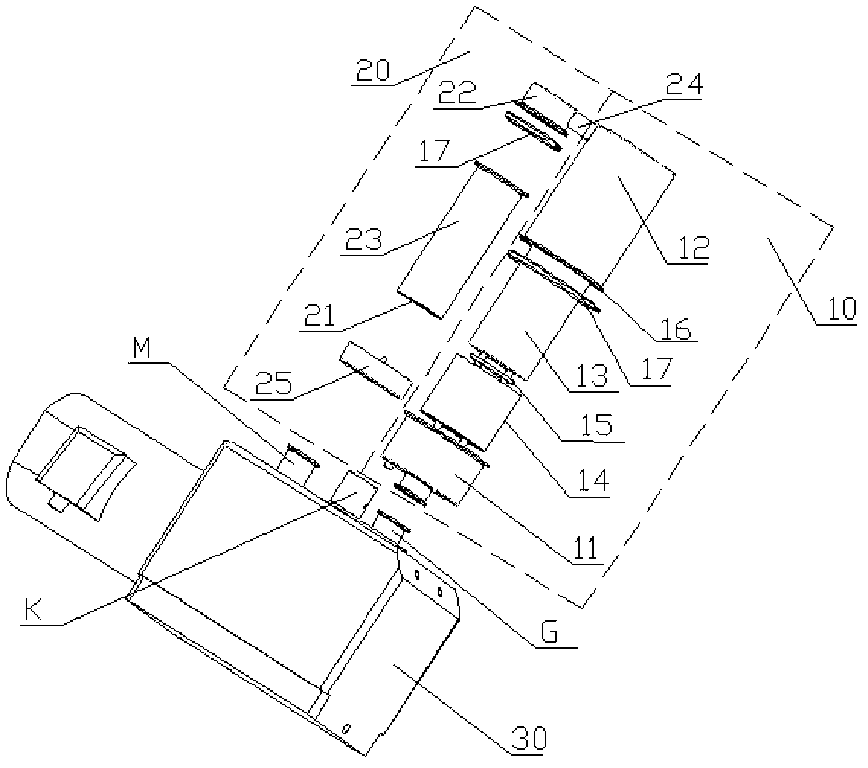
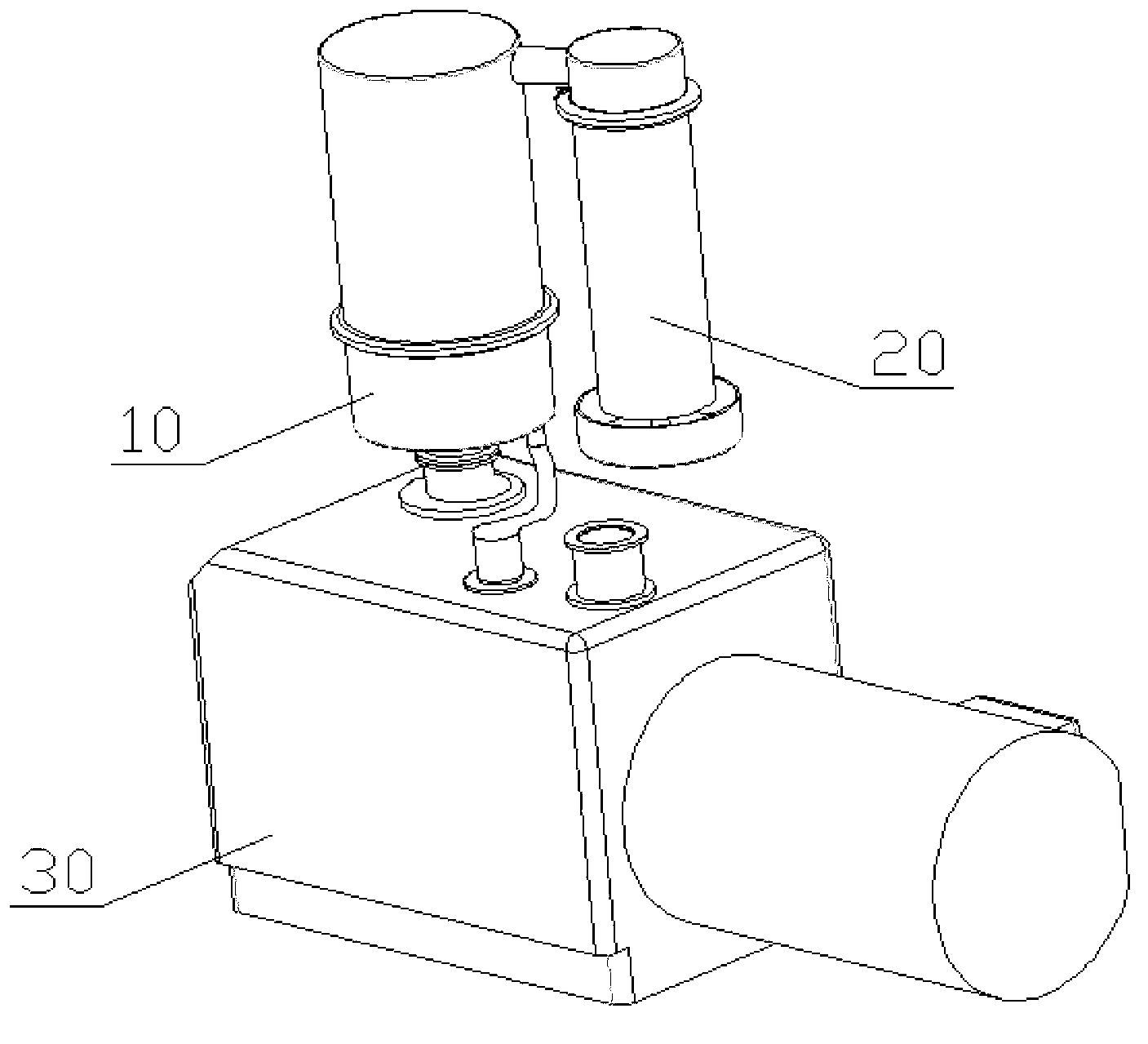
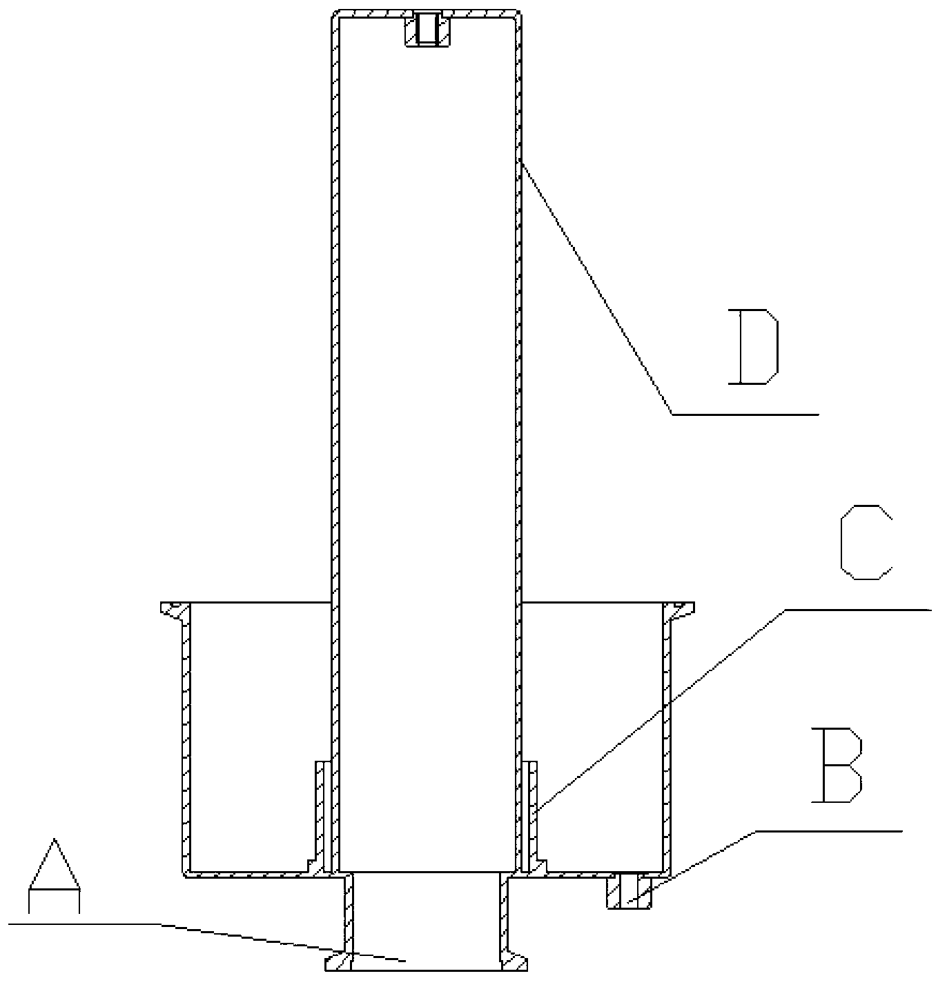
[0029] like Figure 1 to Figure 5 As shown, the first specific embodiment of the present invention is: a waste gas decomposition device of a hydrogen peroxide plasma sterilizer, which is vertically installed on the vacuum pump of the hydrogen peroxide low-temperature plasma sterilizer, including lubricating oil recovery System 10 and exhaust gas purification system 20, the lubricating oil recovery system 10 is composed of lower casing 11, upper casing 12, filter element 13 and condensation cover 14, the lower casing 11, upper casing 12 and condensation cover 14 are all made of stainless steel Production, an air inlet A and a return port B are provided at the end of the lower housing 11, the air inlet A is connected to the exhaust hole G of the vacuum pump 30, and the return port B is connected to the return hole K of the vacuum pump 30. Filter element 13 is columnar, adopts hollow structure, and its one end is open, and the filter layer of filter element 13 uses macromolecular...


PUM


Abstract

The invention discloses an exhaust gas decomposer of a hydrogen peroxide plasma sterilizer, which comprises a lubricating oil recovery system (10) and an exhaust gas cleaning system (20), wherein the lubricating oil recovery system (10) comprises a lower shell (11), an upper shell (12) and a filter element (13), a gas inlet (A) and a reflux inlet (B) are arranged in the end part of the lower shell (11); the exhaust gas cleaning system (20) comprises a cleaning barrel and a recovering box (25), activated carbon particles are arranged in the cleaning barrel, mixed oil gas exhausted from a vacuum pump gas vent (G) enters the exhaust gas decomposer through the gas inlet (A) of the lower shell (11) of the lubricating oil recovery system, lubricating oil returns to a vacuum pump (3) after being adsorbed through the filter element (13), the hydrogen peroxide exhaust gas is decomposed into oxygen and water through adsorption of the activated carbon particle, then the oil gas separation is completed, and the recycling of the lubricating oil and the cleaning of the hydrogen peroxide exhaust gas are realized.

Description

technical field [0001] The invention relates to a sterilization equipment, especially a hydrogen peroxide low-temperature plasma sterilizer, in particular an oil-gas separation and waste gas decomposition device suitable for a hydrogen peroxide low-temperature plasma sterilizer, which belongs to disinfection and sterilization The field of equipment technology belongs to the international patent classification number A61L. . Background technique [0002] In the medical field, the disinfection and sterilization of medical devices is particularly important. The sterilization methods are generally divided into high temperature and low temperature. The method of low-temperature disinfection and sterilization of medical instruments is hydrogen peroxide low-temperature plasma sterilization. The specific method is to place the medical instruments to be sterilized in the sterilization chamber of hydrogen peroxide low-temperature plasma sterilization equipment, and In the low-pressu...

Claims


Application Information

Patent Timeline
IPC IPC(8): B01D53/76B01D53/46C10M175/00
Inventor 刘勇张泽立张廷位章翼青奉李汪洋徐鸿
Owner LAOKEN MEDICAL TECH
Why Eureka
Try Eureka