
Salt discharge treatment system for salted reservoir, building method and treatment method for salted water

A technology of treatment system and construction method, applied in water/sludge/sewage treatment, chemical instruments and methods, water/sewage multi-stage treatment, etc. Beneficial for cleaning water collecting cage and crushed stone base

Inactive Publication Date: 2013-11-13
TIANJIN WATER RESOURCES RES INST
View PDF4 Cites 0 Cited by
  • Summary
  • Abstract
  • Description
  • Claims
  • Application Information

AI Technical Summary

Problems solved by technology

[0003] The main purpose of the present invention is to solve the problem of salinization of the stored water in the dry pond in the above-mentioned reservoir, and provide a salty water discharge treatment system and construction method of the salty water reservoir and a salty water treatment method

Method used


Image

  • Salt discharge treatment system for salted reservoir, building method and treatment method for salted water
  • Salt discharge treatment system for salted reservoir, building method and treatment method for salted water
  • Salt discharge treatment system for salted reservoir, building method and treatment method for salted water

Examples


Embodiment 1

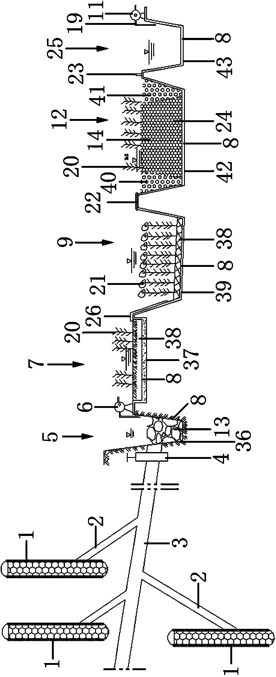
[0074] It consists of a mobile water collection well (1), a water collection cage (18), a water diversion branch pipe (2), a water collection main pipe (3), a water collection well (5), a surface flow wetland (7), a sinking pond (9), Subsurface wetlands (12) and reservoirs (25), mobile water collection wells (1), water collection wells (5), surface flow wetlands (7), sinking ponds (9), subsurface wetlands (12) and water storage Pool (25) is laid out according to actual topography.

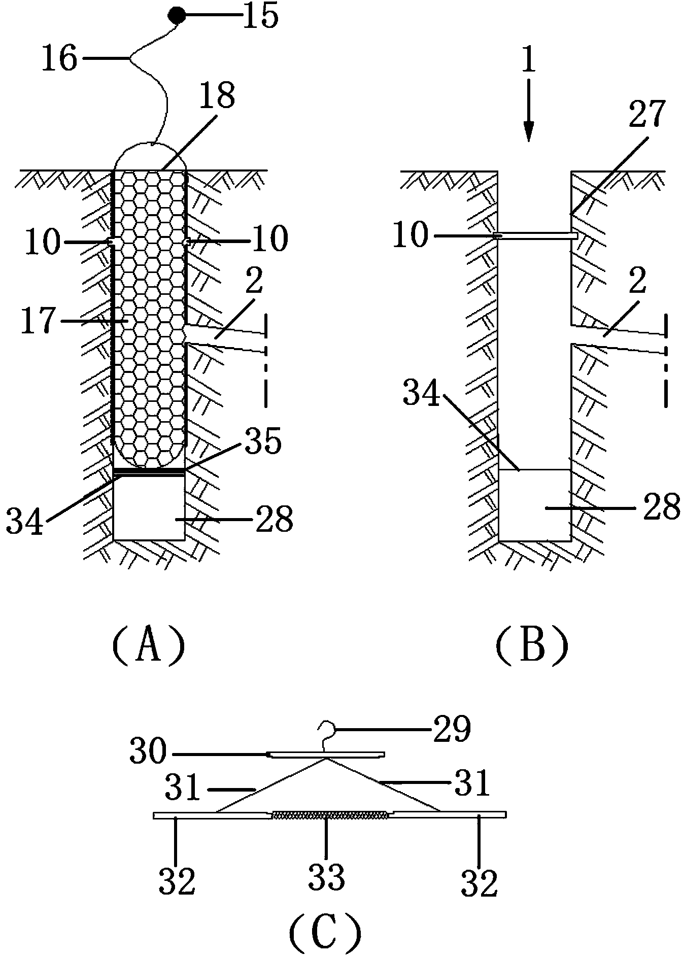
[0075] The mobile water collection well (1) is arranged according to the actual topography of the reservoir, at least one. The mobile water collection well (1) is composed of the main body of the water collection well (27), the water collection cage (18), the identification float (15), and the guide rope (16), support bracket (34), positioning clamping plate mechanism (35), silt sedimentation area (28) and crushed stone base material (17), the main body of the water collection well (27) is set at t...

Embodiment 2

[0081] The bottom of the water collecting cage (18) is provided with a positioning clamp mechanism (35), and the positioning clamp mechanism (35) is composed of a hook (29), a center plate (30), a sliding rod (31), a side wing plate (32) and a spring (33) form, the upper part of center plate (30) is fixedly provided with hook (29), and hook (29) is hung on the bottom center of water collecting cage (18), and hook (29) and center plate (30) along with water collecting The cage (18) rises or falls, and the lower part of the central plate (30) is provided with sliding rods (31), at least two sliding rods (31), and the upper end of the sliding rods (31) is connected with the lower part of the central plate (30), sliding The lower ends of the rods (31) are respectively connected to the upper parts of the flank plates (32) on both sides, the inner sides of the two flank plates (32) are opposite, and the hooks (29) and the central plate (30) follow the water collecting cage (18) The ...

Embodiment 3

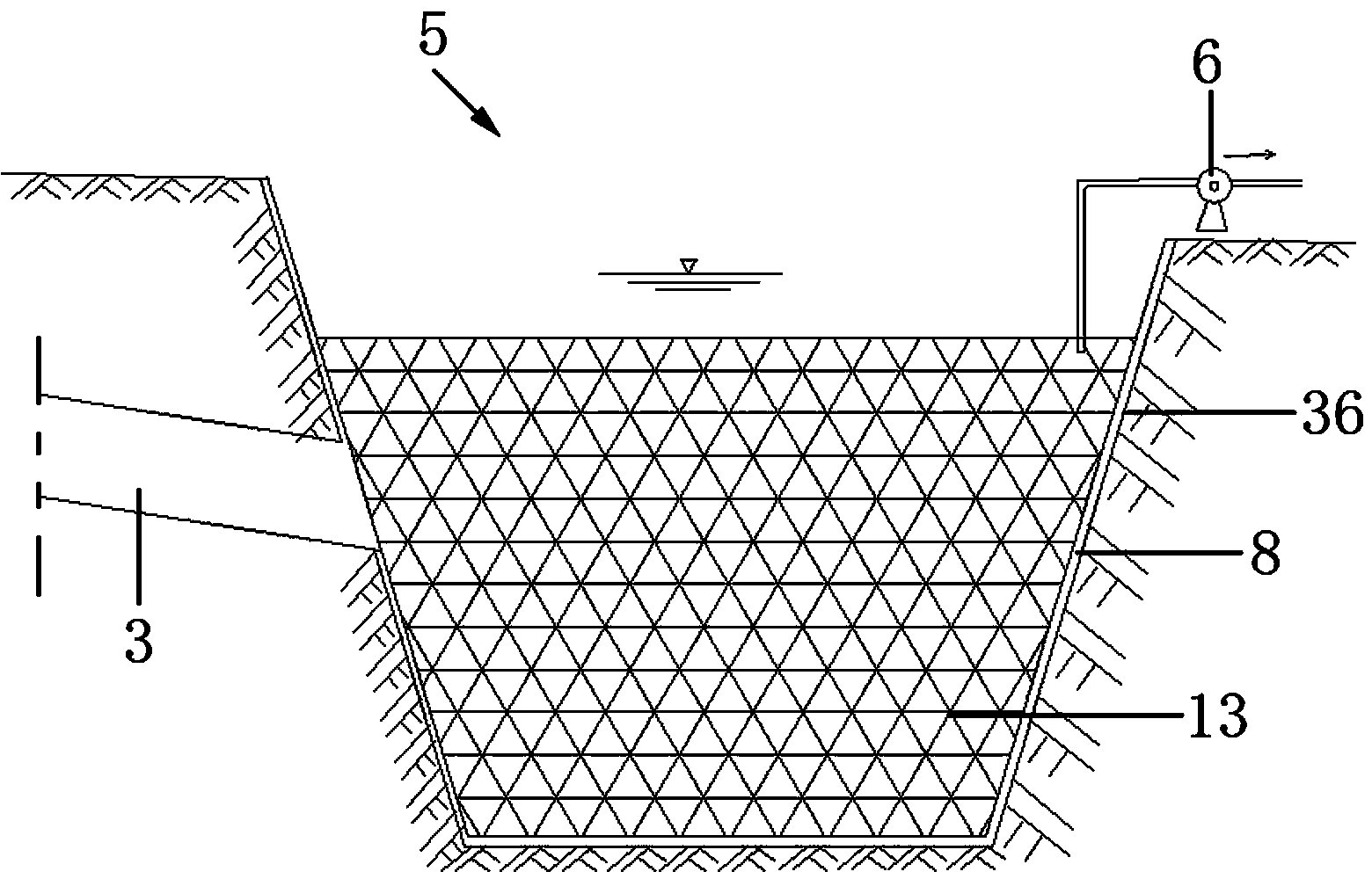
[0085] The water collection well (5) is composed of the water collection well main body (36), the water collection main pipeline (3), the waterproof layer (8), the filter base material (13) and the lift pump (6), the water collection well main body of the water collection well (5) (36) The overall shape is trough, and the overall cross-sectional area is rectangular, circular, triangular, polygonal and irregular polygonal. At least one type is used. The slope of the well wall of the water collection well (5) is slope-shaped, and the water collection well (5) is In the fully anti-seepage collecting well, a waterproof layer (8) is laid in the wall of the water receiving well (5) and in the bottom of the well to prevent the water source from penetrating into the groundwater and causing water pollution. The filter base material (13) is set in the well of the water collection well (5), the filter base material (13) is gravel, and the crushed stone particle size is 20-60mm, the bottom...


PUM

PropertyMeasurementUnit
particle diameteraaaaaaaaaa

Abstract

The invention discloses a salt discharge treatment system for a salted reservoir, a building method, and a treatment method for salted water. The salt discharge treatment system consists of movable water collecting wells, water collecting cages, water diversion branch pipes, a main water collecting pipe, a water gathering well, surface flow wetland, a water sinking pond, subsurface wetland and a water storage reservoir, wherein the movable water collecting wells, the water gathering well, the surface flow wetland, the water sinking pond, the subsurface wetland and the water storage reservoir are laid out according to an actual physiognomy; the water gathering well, the surface flow wetland, the water sinking pond, the subsurface wetland and the water storage reservoir are totally seepage-proof water collecting wells, and the salted water is collected by the movable water collecting wells, treated in the wetlands and the water sinking pond and stored in the water storage reservoir for other purposes. The salt discharge treatment system is reasonable in structure, scientific in design, investment-saving, short in construction period, low in water treatment cost and convenient to manage, takes effect fast, can conduct purification treatment at all seasons, produces high-quality water, recovers a self-purification function of a water body, can be used for supplying landscape water, can be closely combined with city landscape construction, realizes water purification, and achieves purposes of conservation and efficient utilization of water resources.

Description

technical field [0001] The invention relates to a sewage treatment system, in particular to a saline reservoir discharge salt treatment system, a construction method and a saline water treatment method. Background technique [0002] At present, there are many reservoirs in the coastal areas of our country, most of which are built on the land retreating from the sea. The subsoil at the bottom of the reservoirs has high salt content, complex terrain, and a large number of dry ponds and highlands. Due to the long-term retention, evaporation, and high salt content of the bottom soil, the stored water in the dry ponds is seriously salinized. When water is transferred to the reservoir, the newly transferred water source will be mixed with the high-salt water storage, causing the salt content of the water body in the reservoir to increase sharply, and the water body is seriously salinized, causing the reservoir to lose its water source function. Contents of the invention [0003...

Claims


Application Information

Patent Timeline
Patent Type & Authority Patents(China)
IPC IPC(8): C02F9/14E02B1/00
Inventor 常素云刘学功张凯任必穷刘京晶刘波杨洁
Owner TIANJIN WATER RESOURCES RES INST
Learn More