Steam fabric setting machine cascade waste heat comprehensive utilization system of printing and dyeing mill

A technology of setting machine and printing and dyeing factory, which is applied in the direction of steam generation, lighting and heating equipment, and equipment configuration for processing textile materials. Utilization efficiency, reduction of energy consumption, and effects of solving power shortages

Active Publication Date: 2014-07-09
ZHEJIANG JIABAO ENERGY SAVING TECH
View PDF7 Cites 0 Cited by
  • Summary
  • Abstract
  • Description
  • Claims
  • Application Information

AI Technical Summary

Problems solved by technology

However, the coal-fired heat-conducting oil boilers used by general printing and dyeing enterprises have low thermal efficiency, high dust removal and desulfurization rate, and relatively high unit investment, which is not conducive to energy saving and emission reduction. Moreover, the performance of heat-conducting oil will decline with time, and it needs to be replaced regularly and maintained. High cost; and there is a risk of fire at high temperature, so it is necessary and urgent to be replaced
At present, some enterprises have begun to use natural gas for finalization. Natural gas directly enters the workshop and burns directly in the equipment. Leakage points are difficult to find, and there is a high possibility of fire and explosion. It is not the first choice for finalization.

Method used


Image

  • Steam fabric setting machine cascade waste heat comprehensive utilization system of printing and dyeing mill
  • Steam fabric setting machine cascade waste heat comprehensive utilization system of printing and dyeing mill
  • Steam fabric setting machine cascade waste heat comprehensive utilization system of printing and dyeing mill

Examples


Embodiment Construction

[0022] The present invention will be further described below in conjunction with specific examples, but the protection scope of the present invention is not limited thereto.

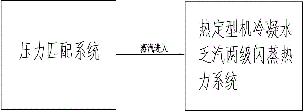
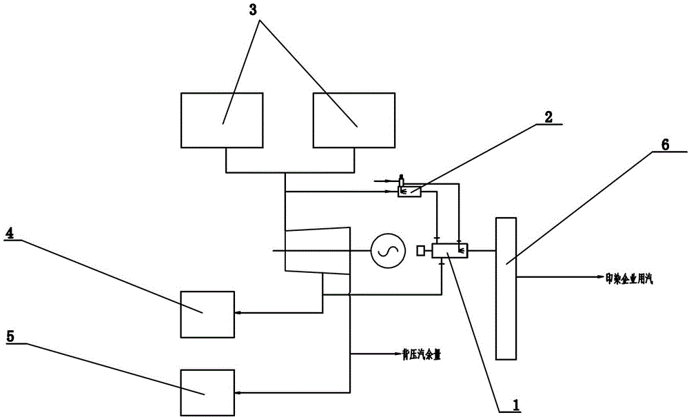
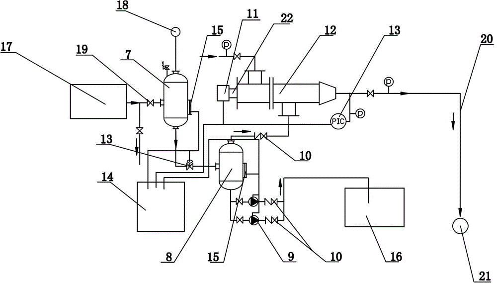
[0023] Such as figure 1 and figure 2 As shown, the cascade waste heat comprehensive utilization system of the steam fabric setting machine in the printing and dyeing factory of the present invention includes a heat setting machine condensed water exhaust steam two-stage flash thermal system connected with the pressure matching system, and a heat setting machine condensed water exhaust steam two-stage flash evaporation The thermal system includes heat setting machine condensed water collection device 17, control device, multi-stage flash evaporation device, electric actuator 11 and high temperature anti-cavitation water pump 9, heat setting machine condensed water collection device 17 is connected with multi-stage flash evaporation through pipelines Device; the multi-stage flash device is respectively c...


PUM


Abstract

The invention discloses a steam fabric setting machine cascade waste heat comprehensive utilization system of a printing and dyeing mill. The system comprises a heat setting machine condensed water steam exhaust two-level flashing thermodynamic system communicated with a pressure matching system, wherein the heat setting machine condensed water steam exhaust two-level flashing thermodynamic system comprises a heat setting machine condensed water collecting device, a control device, a multi-level flashing device, an electronic executing mechanism and a high-temperature cavitation-proof water pump; the heat setting machine condensed water collecting device is communicated with the multi-level flashing device through pipelines; the multi-level flashing device is respectively communicated with a steam (back pressure) heating network, a relay pump station and a multi-nozzle heat pump; and the multi-nozzle heat pump is communicated with a cylinder through a low-pressure steaming pipeline. By adopting the two-level flashing, the air inlet pressure of the setting machine can be controlled through a steam pressure matching machine; different sizing temperature needed by various fabrics can be acquired; the electricity consumption of conductive oil boilers of the printing and dyeing enterprise can be reduced; the environment stress can be alleviated; the thermalized power generation of the thermal power plant is increased; and the power shortage can be effectively solved.

Description

technical field [0001] The invention provides a cascade waste heat comprehensive utilization system of a steam fabric setting machine in a printing and dyeing factory, which uses concentrated medium-pressure steam instead of heat-conducting oil for qualitative determination. Background technique [0002] Printing and dyeing enterprises are large consumers of heat and electricity, and require a large amount of heating steam in the process of printing, dyeing and finishing. There are currently 212 printing and dyeing enterprises in Shaoxing County (there are 250 heat-supply single and independent table users in thermal power plants), and more than 95% of the printing and dyeing enterprises have adopted central heating, but the steam for conventional heating has a low heating pressure, and its saturated steam temperature is also low. Low (generally less than 160°C), the setting temperature of chemical fiber fabrics must reach at least 180°C, and the heat of steam is mainly the ...

Claims


Application Information

Patent Timeline
Patent Type & Authority Patents(China)
IPC IPC(8): D06B23/20F22B3/04
Inventor 王红亚蔡云来席云波
Owner ZHEJIANG JIABAO ENERGY SAVING TECH
Why Eureka
Try Eureka