
High-frequency electromagnetic steam engine

A high-frequency electromagnetic and steam engine technology, used in steam generation, steam generation methods, lighting and heating equipment, etc., can solve the problems of large steam water content and high thermal efficiency, and achieve compact equipment structure, reduced floor space, and energy utilization. high effect

Active Publication Date: 2013-04-03
缪桂道
View PDF5 Cites 6 Cited by
  • Summary
  • Abstract
  • Description
  • Claims
  • Application Information

AI Technical Summary

Problems solved by technology

[0004] The purpose of the present invention is to provide a high-frequency electromagnetic steam engine, which is a high-frequency electromagnetic steam engine without a water level gauge, thereby overcoming the defects of high-temperature, low-pressure and high-temperature, high-pressure steam with high water content in the prior art, without the need for heat conduction oil, higher thermal efficiency

Method used


Image

  • High-frequency electromagnetic steam engine
  • High-frequency electromagnetic steam engine
  • High-frequency electromagnetic steam engine

Examples


Embodiment 1

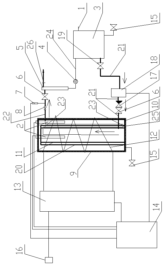
[0023] Such as figure 1 The shown electromagnetic steam engine includes a water supply system, a tank body 10, a water inlet pipeline 21 and a steam pipeline 22 respectively communicated with the inside of the tank body, a high-frequency electromagnetic coil 12 wound around the periphery of the tank body 10, and a high-frequency electromagnetic coil. A high-frequency electromagnetic generator 13 connected to the coil, a steam temperature sensor 2 installed in the tank, and a PLC electronic control system 14 for processing the temperature and pressure of the steam and automatically controlling the equipment. The steam pipeline is connected with a steam pressure sensor 7 , and the high-frequency electromagnetic generator 13 , the steam temperature sensor 2 and the steam pressure sensor 7 are respectively connected with a PLC electric control system 14 . The high-frequency electromagnetic generating device 13 is connected to a power source 16 .

[0024] The tank body 10 is wrapp...

Embodiment 2

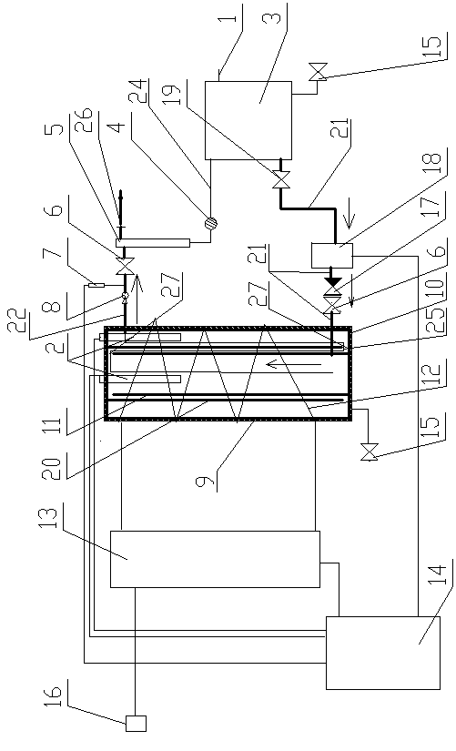
[0031] Such as figure 2 Shown a kind of electromagnetic steam engine, specific structure is the same as embodiment 1, and difference is the structure and the arrangement mode of inner sleeve and middle sleeve, specifically as follows:

[0032] Both the middle sleeve 20 and the inner sleeve 11 are cylindrical bodies with upper and lower openings, the top of the middle sleeve 20 is connected to the top of the tank body, and the bottom of the inner sleeve 11 is fixedly connected to the bottom of the tank body. The top of the inner sleeve and the upper surface of the tank, the bottom of the middle sleeve and the lower surface of the tank respectively leave a gap 27 for the passage of steam, and the steam and water vapor generated in the inner sleeve flow out through the gap 27, that is, the inner sleeve The gap at the top of the barrel and the gap at the lower end of the middle sleeve form a baffle passage 25 for steam to flow.

Embodiment 3

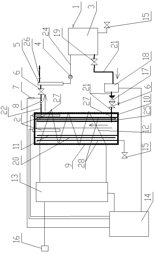
[0034]An electromagnetic steam engine, the specific structure is the same as in Example 1, the difference is that the outer diameter of the tank body described in this embodiment is 120 mm, and the thickness of the tank body is 8 mm; the outer diameter of the inner sleeve is 50 mm, and the thickness of the tank body is 8 mm. 3mm; the outer diameter of the intermediate sleeve is 90mm, and the thickness of the tank body is 4.5mm.


PUM


Abstract

The invention belongs to the technical field of heating devices and relates to a high-frequency electromagnetic steam engine. The defect that high-temperature and low-pressure steam and high-temperature and high-pressure steam are high in water content in the prior art is overcome by the invention. Conduction oil is not needed, and the thermal efficiency is higher. The high-frequency electromagnetic steam engine comprises a water supply system, a tank, a water inlet pipeline and a steam pipeline, wherein the water inlet pipeline and the steam pipeline are respectively communicated with the interior of the tank. The high-frequency electromagnetic steam engine also comprises a high-pressure electromagnetic coil, a high-pressure electromagnetic generating device, a steam temperature sensor and a programmable logic controller (PLC) electronic control system, wherein the high-pressure electromagnetic coil is wound at the periphery of the tank; the high-pressure electromagnetic generating device is mutually connected with the high-pressure electromagnetic coil; the steam temperature sensor is arranged in the tank; the PLC electronic control system is used for performing automatic control on the temperature and the pressure of the steam to be treated and equipment; the steam pipeline is connected with a steam pressure sensor; and the high-pressure electromagnetic generating device, the steam temperature sensor and the steam pressure sensor are respectively and mutually connected with the PLC electronic control system. The steam is generated by utilizing electromagnetic energy, so that the high-frequency electromagnetic steam engine is high in thermal efficiency, is environmentally friendly and is convenient in maintenance.

Description

technical field [0001] The invention belongs to the technical field of heating devices, and relates to a high-frequency electromagnetic steam engine. Background technique [0002] A boiler heated by heat transfer oil is called a heat transfer oil boiler. Heat transfer oil, also known as organic heat carrier or heat medium oil, has been used as an intermediate heat transfer medium in industrial heat exchange processes for more than 50 years. The heat transfer oil boiler is a once-through boiler developed based on the design idea of ​​forced circulation. The sealed new cycle heat supply is connected to the atmosphere, which can prolong the service life of the boiler, and the liquid phase or gas phase conveys heat supply. The heat-conducting oil boiler adopts a three-pass coil design, and the system sets an expansion water tank to realize low-pressure and high-temperature heating. The coil structure is adopted, the heating surface is sufficient, and the expansion is fully ab...

Claims


Application Information

Patent Timeline
Patent Type & Authority Applications(China)
IPC IPC(8): F22B1/28
Inventor 缪桂道
Owner 缪桂道
Learn More