
Device and method for determination of oil gas minimum miscibility pressure through magnetic resonance imaging technology

A technology of magnetic resonance imaging and miscible pressure, which is applied to measurement devices, fluid pressure measurement, specific gravity measurement, etc., can solve the problems of inconsistent judgment standards for miscibility, large errors, and time-consuming, and achieve the effect of visualization

Inactive Publication Date: 2013-04-03
DALIAN UNIV OF TECH
View PDF4 Cites 13 Cited by
  • Summary
  • Abstract
  • Description
  • Claims
  • Application Information

AI Technical Summary

Problems solved by technology

The most commonly used method is the narrow tube method, which has developed into a standard method in engineering, but its measurement process is complicated, time-consuming, economical, and the judgment standard for miscibility is not uniform; secondly, the bubble riser method, the device is simple , good economy, and faster, but it is not a quantitative measurement, and the error is larger than other methods; in recent years, the newly developed interfacial tension disappearance method takes advantage of the characteristic that the interfacial tension disappears to zero when oil and gas are mixed, by measuring gas and oil The interfacial tension versus pressure curve is used to judge the minimum miscible pressure point. This method only focuses on the single physical quantity of interfacial tension and requires a large number of tests of standard complex gas-liquid systems, which still has certain limitations.

Method used


Image

  • Device and method for determination of oil gas minimum miscibility pressure through magnetic resonance imaging technology
  • Device and method for determination of oil gas minimum miscibility pressure through magnetic resonance imaging technology
  • Device and method for determination of oil gas minimum miscibility pressure through magnetic resonance imaging technology

Examples


Embodiment

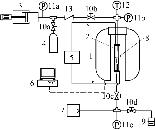
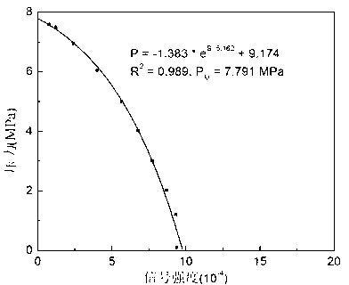
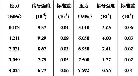
[0031] At 37.8°C, choose CO 2 / n-decane system to do the minimum miscible pressure experiment. Put 0.5ml of n-decane in a flat-bottomed test tube, place it in a high-pressure container, and obtain the signal intensities of the proton density maps of the oil phase under different pressures according to the first and second steps above, as shown in the table below. exist figure 2 In , the data points are fitted to obtain an exponential relationship curve between signal intensity and pressure. The intersection point of the curve and the pressure axis corresponds to the pressure value, which is the CO 2 The minimum miscible pressure with n-decane at 37.8°C.

[0032]

[0033]


PUM


Abstract

Belonging to the technical field of chemical engineering and petroleum engineering, the invention relates to a device and a method for determination of an oil gas minimum miscibility pressure through a magnetic resonance imaging technology. The device mainly comprises a magnetic resonance imaging system and a gas injection system. For the magnetic resonance imaging system, a pressure vessel is arranged in a magnetic resonance imaging instrument, a flat bottom test tube is positioned in the high pressure vessel, and the magnetic resonance imaging instrument is electrically connected to a data acquisition and processing system. The method for determining the minimum miscibility pressure of gas and oil firstly makes use of a magnetic resonance imaging technology to determine the signal strength distribution of oil in the flat bottom test tube so as to obtain a signal strength change curve of oil in gas and liquid phases within an imaging visual field under certain temperature along with the variation of pressure. By determining the intersection point of the signal strength curve and a pressure axis, the minimum miscibility pressure of gas and oil can be obtained. The method can determine the minimum miscibility pressure of gas and oil and enhance the understanding on the gas-liquid two-phase equilibrium law of gas and oil, thus being able to provide basic physical property data for underground multiphase multicomponent migration law analysis of light hydrocarbon and CO2 tertiary oil recovery.

Description

technical field [0001] The invention relates to a device and method for measuring the minimum miscible pressure of oil and gas by using magnetic resonance imaging technology, belonging to the technical fields of chemical engineering and petroleum engineering. Background technique [0002] The minimum miscible pressure is the minimum pressure at which oil and gas are miscible into a single phase at a certain temperature. It is accurate and quick to measure the minimum miscible pressure of gas and oil. For gas injection (CO 2 , light hydrocarbons, etc.) engineering research on enhanced oil recovery, miscible and immiscible displacement evaluation, economical design of oil recovery, and effective storage of greenhouse gases has important guiding significance. Gas flooding technology can further increase oil recovery by 10%-15% on the basis of conventional technology. 2 It is necessary to provide basic physical property data for the analysis of underground multi-phase and multi...

Claims


Application Information

Patent Timeline
IPC IPC(8): G01N9/36G01L11/00
Inventor 宋永臣朱宁军赵越超刘瑜杨明军蒋兰兰王同雷郑鸿飞宿博
Owner DALIAN UNIV OF TECH
Learn More