Lactate sensor
A sensor, lactic acid technology, applied in the field of lactic acid sensor, can solve the problems of slow enzyme reaction speed, shortened measurement time, long time, etc., and achieve the effect of excellent precision
- Summary
- Abstract
- Description
- Claims
- Application Information
AI Technical Summary
Problems solved by technology
Method used
Image
Examples
Embodiment approach
[0071] [1] A lactic acid sensor comprising: an insulating substrate, an electrode system including at least a working electrode and a counter electrode disposed on the substrate, and a reagent layer disposed on the electrode system,
[0072] The reagent layer contains lactate oxidase, mediator, and N-(2-acetamido)-2-aminoethanesulfonic acid.
[0073] [2] The lactic acid sensor according to [1], wherein the reagent layer further contains a sugar selected from the group consisting of oligosaccharides and polysaccharides.
[0074] [3] The lactic acid sensor according to [2], wherein the sugar is dextran or maltose, preferably dextran.
[0075] [4] The lactic acid sensor according to any one of [1] to [3], wherein the reagent layer further contains a layered inorganic compound and / or a surfactant.
[0076] [5] The lactic acid sensor as described in any one of [1] to [4], wherein the mediator is selected from potassium ferricyanide, cytochrome C, pyrroloquinoline quinone, NAD + 、...
Embodiment 1
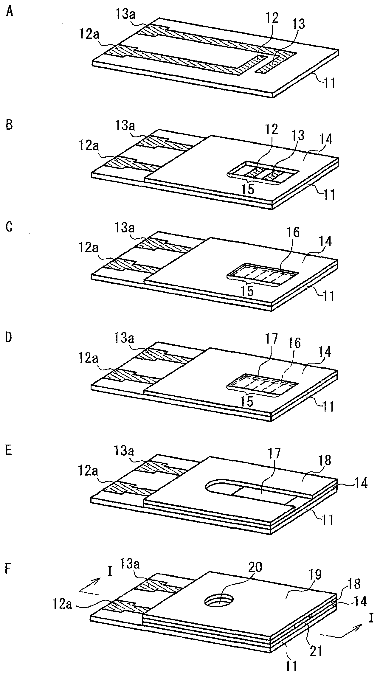
[0096] Produced as shown below with figure 1 The lactate sensor shown has the same structure as the lactate sensor of Example 1.
[0097] First, as the insulating substrate 11 of the lactic acid sensor, a PET substrate (50 mm in length, 6 mm in width, and 250 m in thickness) was prepared, and on one surface thereof, a working electrode 12 having lead portions 12 a and 13 a were formed by screen printing. And the carbon electrode system that the counter electrode 13 constitutes.
[0098] Then, the insulating layer 14 is formed on the electrode system as follows. First, an insulating resin polyester was dissolved in a solvent carbitol acetate to have a concentration of 75% by weight to prepare an insulating paste, which was screen printed on the electrode system. The printing conditions are: 300-mesh screen, 40kg scraper pressure, and the printing volume is per 1cm 2 The electrode area is set to 0.002mL. In addition, screen printing is not performed on the detection part 15 ...
Embodiment 2
[0109] A lactic acid sensor was fabricated in the same manner as in Example 1, except that the second reagent solution contained 0.5% by weight of dextran (molecular weight: 5000-10000, trade name "Dextran", Nacalai Tesque). Using the lactic acid sensors of Examples 1 and 2, venous whole blood with adjusted lactic acid concentration (lactate concentration: 4, 6, 10, 18, 24 mg / dL) was used as a sample, and the measurement temperature conditions were set at 25°C or 10°C , except that, the measurement of lactic acid was carried out in the same manner as in Example 1. express the result in Figure 4 middle. Figure 4 A is a graph of the measured temperature condition of 25°C, Figure 4 B is a graph where the measurement temperature condition is 10°C. Figure 4 In A and B, square marks represent the graph of the lactic acid sensor of Example 1, and rhombus marks represent the graph of the lactic acid sensor of Example 2.
[0110] It was confirmed that both of the lactic acid se...
PUM
 Abstract
Description
Claims
Application Information
 - R&D
- Intellectual Property
- Life Sciences
- Materials
- Tech Scout
- Unparalleled Data Quality
- Higher Quality Content
- 60% Fewer Hallucinations
Browse by: Latest US Patents, China's latest patents, Technical Efficacy Thesaurus, Application Domain, Technology Topic, Popular Technical Reports.
© 2025 PatSnap. All rights reserved.Legal|Privacy policy|Modern Slavery Act Transparency Statement|Sitemap|About US| Contact US: help@patsnap.com


