Cable single-ended travelling wave distance measurement method using fault signature frequency bands and TT conversion

A technology of fault characteristics and distance measurement method, applied in the direction of fault location, etc., can solve problems such as error, dispersion, and inconsistency of attenuation degree of different frequency components, and achieve the effect of improving distance measurement accuracy and reducing error

Inactive Publication Date: 2013-04-03
KUNMING UNIV OF SCI & TECH
View PDF7 Cites 25 Cited by
  • Summary
  • Abstract
  • Description
  • Claims
  • Application Information

AI Technical Summary

Problems solved by technology

The transient fault traveling wave propagating along the line when the line is faulty has a continuous spectrum from low frequency to high frequency. The propagation speed of different frequency components is different. Arrive at the measurement point first, and other frequency components arrive at the measurement point after a certain time delay, so the traveling wave head detected at the measurement point is not an ideal step signal, but a slope-pull function, resulting in the arrival of the wave head The time error of measuring end calibration is large
The traveling wave propagation velocity of a certain frequency component can be solved according to the line parameters at this frequency, but the wave velocity used in the time domain traveling wave ranging is not the wave velocity at a singl

Method used


Image

  • Cable single-ended travelling wave distance measurement method using fault signature frequency bands and TT conversion
  • Cable single-ended travelling wave distance measurement method using fault signature frequency bands and TT conversion
  • Cable single-ended travelling wave distance measurement method using fault signature frequency bands and TT conversion

Examples


Embodiment 1

[0055] Example 1: Resistive failure.

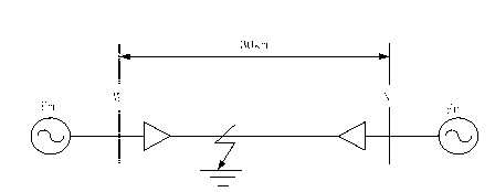
[0056] 110kV cable line structure schematic and layout such as figure 1 As shown, the cable has a total length of 30km. The equivalent impedance of the M-end system is 1.67+j43.18W, and the N-end system impedance is 1.01+j44.92W. In order to remove the influence of the sound line on the identification of the faulty traveling wave head, the length of the sound line is taken as 100km; 2km, A phase ground fault occurred, and the transition resistance was 10Ω.

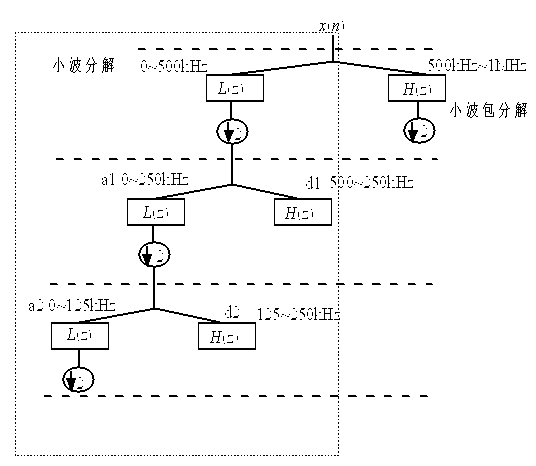
[0057] The first step is to decompose the current traveling wave with db10 orthogonal wavelet, if the maximum scale is 5, such as Figure 4 Shown.

[0058] The second step is to use correlation analysis to calculate the correlation coefficient between the initial traveling wave head and the reflected wave head of the fault point in each frequency band, and define the correlation coefficient The maximum, that is, the frequency band with the greatest similarity between the initial traveling...

Embodiment 2

[0063] Example 2: Arc fault.

[0064] A lot of practical experience shows that the dynamic characteristics of an arc can be simulated by the following differential expression, and an arc model is built. The measured arc characteristics are as Figure 8 , Picture 9 Shown. Figure 8 Is the arc voltage-current characteristic of the cable arc; Picture 9 Is the spectrum of cable arc voltage.

[0065]

[0066] (6)

[0067] (7)

[0068] In equations (6) and (7), Is the arc conductance that changes over time, It reflects the static characteristics of the arc, which can be interpreted as the arc conductance value when the arc current maintains a certain value for a long enough time under constant external conditions. i Is the absolute value of the arc current, It is the arc voltage per unit length of an arc.

[0069] The first step, if the A phase arc ground fault occurs 11km away from the M measuring end, use the db10 orthogonal w...

Embodiment 3

[0075] Example 3: Resistive failure.

[0076] 110kV cable line structure schematic and layout such as figure 1 Shown. The total length of the cable is 30km. The equivalent impedance of the M-end system is 1.67+j43.18W, and the N-end system impedance is 1.01+j44.92W. If the distance to the measuring terminal M is 19km, a phase A ground fault occurs, and the transition resistance is 10Ω.

[0077] The first step is to decompose the current traveling wave with db10 orthogonal wavelet, and the maximum scale is 5.

[0078] The second step is to use correlation analysis to calculate the correlation coefficient between the initial traveling wave head and the reflected wave head of the fault point in each frequency band, and define the correlation coefficient The maximum, that is, the frequency band with the greatest similarity between the initial traveling wave head and the reflected wave head of the fault point is the characteristic frequency band. After calculation, the correlation co...


PUM

PropertyMeasurementUnit
Transition resistanceaaaaaaaaaa

Abstract

The invention relates to a cable single-ended travelling wave distance measurement method using fault signature frequency bands and TT conversion and belongs to the technical field of electrical power system relay protection. Wavelet decomposition is carried out on single-ended travelling wave transient state signals which are then reconfigured into time-domain signals of a plurality of frequency bands, attenuation coefficients and wave velocity of a cable line in each frequency band are relatively fixed, correlation coefficients of initial travelling wave heads (initial wave heads) and fault point reflected wave heads under each frequency band after faults are calculated by adopting relative analysis, the frequency band with maximum correlation coefficients is designed to be a characteristic frequency band, and travelling wave velocity is calculated according to center frequency of the characteristic frequency band. Moment of the travelling wave heads to reach the measurement end is accurately demarcated by using a TT algorithm of time domain conversion in the characteristic frequency band. The cable single-ended travelling wave distance measurement method uses the center frequency of the characteristic frequency band to calculate the travelling wave velocity, reduces errors caused by selection randomicity of the travelling wave velocity in a traditional cable single-ended travelling wave distance measurement technique, is applied to the TT conversion algorithm to demarcate reaching moment of the travelling wave heads, and improves distance measurement accuracy.

Description

technical field [0001] The invention relates to a cable single-end traveling wave ranging method using fault characteristic frequency band and TT transformation, and belongs to the technical field of electric power system relay protection. Background technique [0002] The traditional power cable fault location is generally based on offline measurement, and the biggest problem with the offline method is that some faults are difficult to reproduce under the action of high-voltage impact, resulting in failure of fault location. In addition, multiple injections of high-voltage pulses will damage the defective part of the cable insulation and affect the life of the entire cable. In contrast, online traveling wave ranging has more application prospects. The time calibration of the traveling wave head arriving at the measuring end and the determination of the traveling wave velocity are the key points of traveling wave ranging. The transient fault traveling wave propagating alon...

Claims


Application Information

Patent Timeline
IPC IPC(8): G01R31/08
Inventor 束洪春董俊杨竞及
Owner KUNMING UNIV OF SCI & TECH
Why Eureka
Try Eureka