LED backlight driving circuit, driving method and liquid crystal display device

A backlight drive circuit and backlight drive technology, applied in electrical components, static indicators, instruments, etc., can solve problems such as low output voltage, LED light bar not reaching brightness, and reduced backlight drive efficiency, so as to achieve the effect of improving efficiency

Active Publication Date: 2013-04-03
SHENZHEN CHINA STAR OPTOELECTRONICS TECH CO LTD
View PDF8 Cites 18 Cited by
  • Summary
  • Abstract
  • Description
  • Claims
  • Application Information

AI Technical Summary

Problems solved by technology

Existing backlight drive modules have problems with poor circuit performance. For example, when the LED light bar is lightly loaded (the brightness of the LED light bar is low), it still outputs a large voltage, resulting in...

Method used


Image

  • LED backlight driving circuit, driving method and liquid crystal display device
  • LED backlight driving circuit, driving method and liquid crystal display device
  • LED backlight driving circuit, driving method and liquid crystal display device

Examples


Embodiment 1

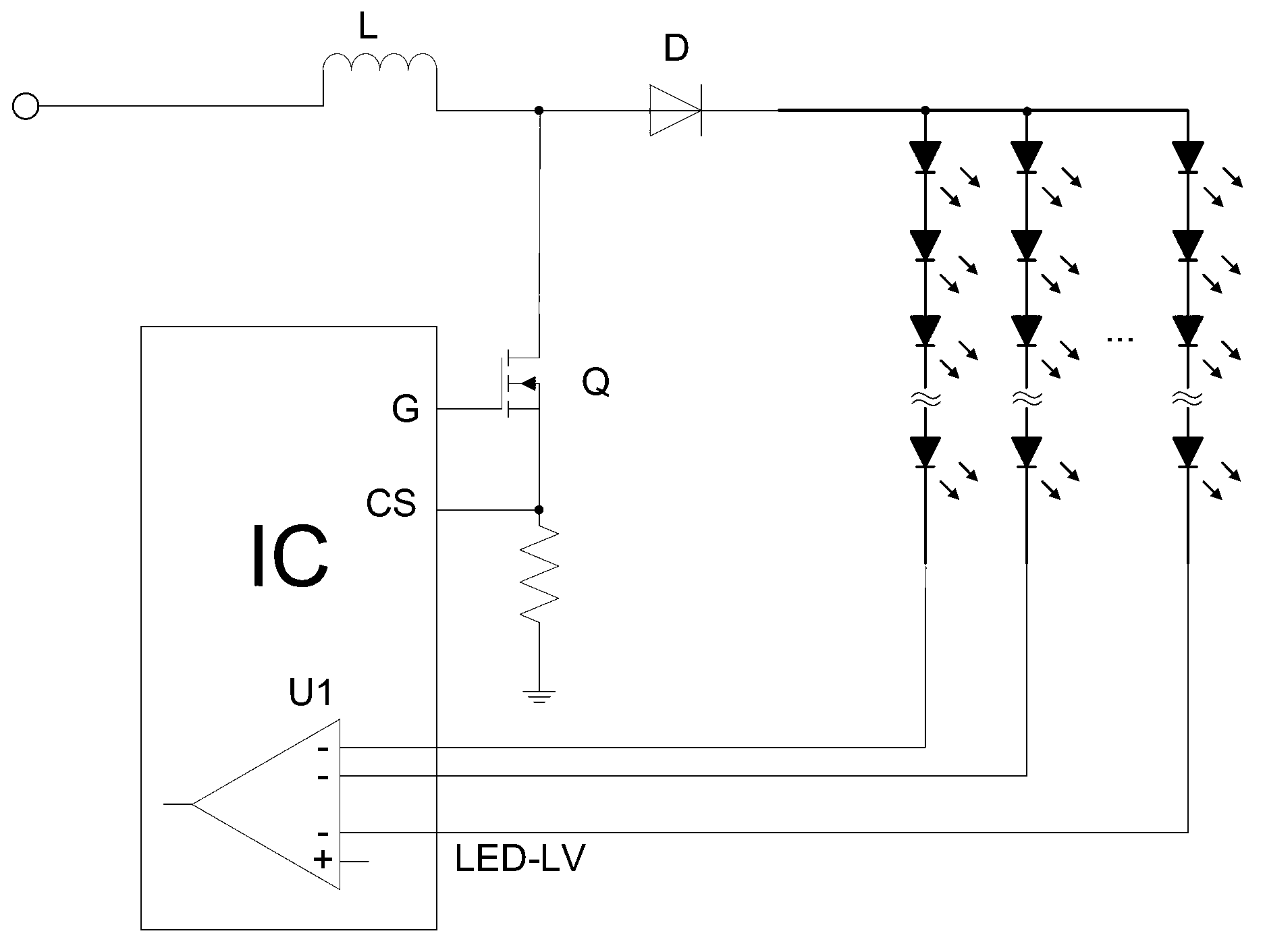
[0057] This embodiment discloses a liquid crystal display device, and the liquid crystal display device includes an LED backlight driving circuit. see Figure 8 , the LED backlight drive circuit includes an LED light bar and a drive module for the LED light bar, the drive module includes a backlight drive chip for adjusting the output voltage of the drive module, the backlight drive chip includes a first comparator for correcting the output voltage of the drive module, and the LED The output terminal of the light bar is coupled to the inverting input terminal of the first comparator; the non-inverting input terminal of the first comparator is coupled with a protection module; the protection module includes a detection unit for detecting the output current of the driving module;

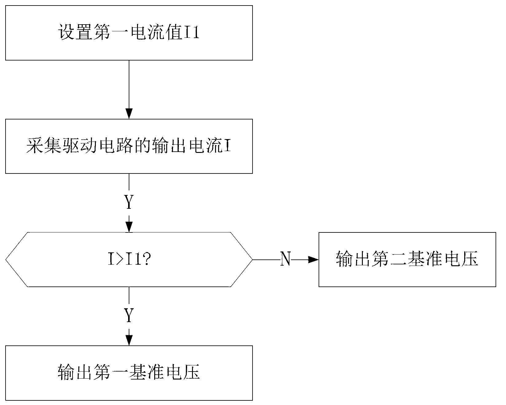
[0058]When the current value detected by the detection unit is higher than the preset first current value, the protection module outputs the first reference voltage to the non-inverting input terminal...

Embodiment 2

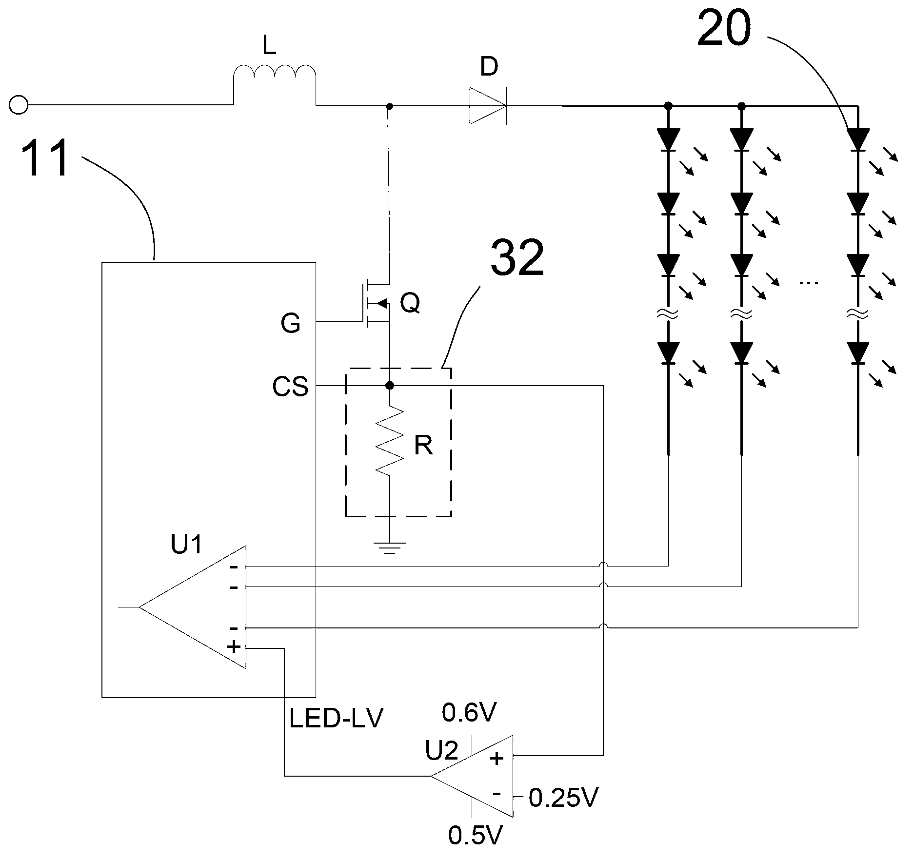
[0063] This embodiment discloses a liquid crystal display device, and the liquid crystal display device includes an LED backlight driving circuit. see figure 2 , the LED backlight drive circuit includes an LED light bar 20 and a drive module 10 for the LED light bar 20 , the drive module 10 for the LED light bar 20 includes an inductor coupled with a power supply, a diode coupled with the inductance, and the cathode of the diode is coupled to the LED light bar 20 The input terminal of the diode, a voltage-regulating controllable switch and a voltage dividing resistor are connected in series between the anode of the diode and the power supply grounding terminal; the driving module 10 includes a backlight driver chip 11 for adjusting the output voltage of the driving module 10, and the voltage-regulating controllable switch The control terminal is coupled to the backlight driver chip 11, the backlight driver chip 11 includes an overcurrent protection pin, the terminal voltage o...

Embodiment 3

[0072] This embodiment discloses a liquid crystal display device, and the liquid crystal display device includes an LED backlight driving circuit. see Figure 4 , an LED backlight driving circuit, comprising an LED light bar 20 and a driving module 10 of the LED light bar 20, the driving module 10 of the LED light bar 20 includes an inductor coupled to a power supply, a diode coupled to the inductor, and a cathode coupled to the LED Between the input end of the light bar 20, the anode of the diode and the ground end of the power supply, a voltage-regulating controllable switch and a voltage-dividing resistor are connected in series; the driving module 10 includes a backlight driving chip 11 for adjusting the output voltage of the driving module 10, and the voltage regulation can The control terminal of the control switch is coupled to the backlight driver chip 11, the backlight driver chip 11 includes an overcurrent protection pin, the terminal voltage of the voltage dividing ...


PUM


Abstract

The invention discloses an LED backlight driving circuit, a driving method and a liquid crystal display device. The LED backlight driving circuit comprises an LED light bar and a driving module of the LED light bar; the driving module comprises a backlight driving chip used for adjusting output voltage of the driving module, the backlight driving chip comprises a first comparator used for correcting the output voltage of the driving module, and an output end of the LED light bar is coupled to an inverted input end of the first comparator; a non-inverted input end of the first comparator is coupled to a protection module; and the protection module comprises a detection unit used for detecting output current of the driving module. When a current value detected by the detection unit is higher than a preset first current value, the protection module outputs first reference voltage to the non-inverted input end of the first comparator; and when the current value detected by the detection unit is lower than the preset first current value, the protection module outputs second reference voltage lower than the first reference voltage to the non-inverted input end of the first comparator. The LED backlight driving circuit, the driving method and the liquid crystal display device have the advantage that the efficiency of the driving module is improved.

Description

technical field [0001] The invention relates to the field of liquid crystal display, and more specifically relates to an LED backlight driving circuit, a driving method and a liquid crystal display device. Background technique [0002] Most existing liquid crystal display devices use LEDs as backlight sources. The specific method is to connect multiple LED lights in series to form an LED light bar, and then couple the LED light bar to a booster circuit. see figure 1 , the controllable switch Q of the boost circuit is coupled to a backlight driver chip IC, and the output voltage of the boost circuit can be adjusted according to the duty cycle of the output signal of the drive pin G of the backlight driver chip, thereby realizing the dimming of the LED light bar . If there are multiple LED strips, they can be connected in parallel to the same boost circuit. There is a comparator inside the backlight driver chip, and the output end of each LED light bar is coupled to the inv...

Claims


Application Information

Patent Timeline
IPC IPC(8): G09G3/34G09G3/36
CPCG09G3/3406H05B45/38H05B45/46Y02B20/30
Inventor 胡安乐杨翔
Owner SHENZHEN CHINA STAR OPTOELECTRONICS TECH CO LTD
Why Eureka
Try Eureka