
Precisely position the silo

A technology of precise positioning and silo, which is applied in metal processing and other directions, can solve the problems of inconvenient workpiece change, poor repeat positioning accuracy, and less loaded workpieces, and achieve short installation and debugging time, high repeat positioning accuracy, accurate material retrieving and The effect of discharging

Active Publication Date: 2016-08-03
CHONGQING MACHINE TOOL GROUP
View PDF11 Cites 0 Cited by
  • Summary
  • Abstract
  • Description
  • Claims
  • Application Information

AI Technical Summary

Problems solved by technology

[0007] In view of this, the present invention provides a precise positioning silo, one of its purposes is to solve the problem of poor repeated positioning accuracy in the horizontal direction of the silo, which leads to inaccurate material grabbing by machine tools or manipulators; the second purpose is to solve the problem of workpiece tooth thickness The deviation leads to the problem of large cumulative deviation in the vertical direction; the third purpose is to solve the problem that there are few workpieces loaded and the workpieces cannot be stacked in multiple layers; the fourth purpose is to solve the problem of inconvenient workpiece change; the fifth purpose is to solve the problem of The problem of long installation and commissioning time of the silo; the sixth purpose is to solve the problem that the silo occupies too much area

Method used


Image

  • Precisely position the silo
  • Precisely position the silo
  • Precisely position the silo

Examples


Embodiment Construction

[0030] The present invention will be further described below in conjunction with the accompanying drawings and embodiments.

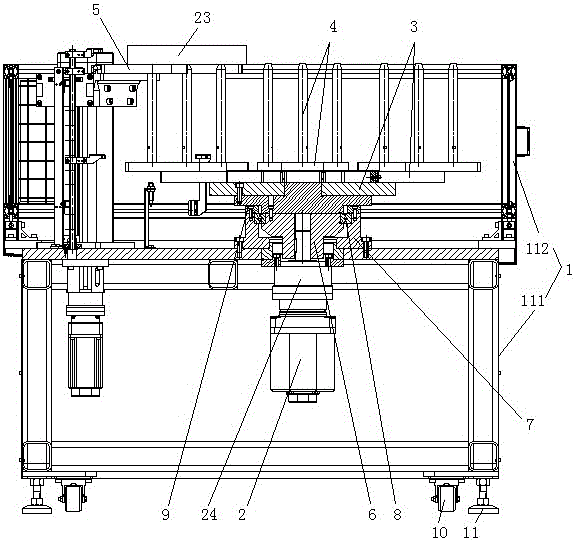
[0031] As shown in the figure, this embodiment accurately positions the silo, including a silo frame 1, a workpiece lifting mechanism and a workpiece horizontal rotating transport mechanism;

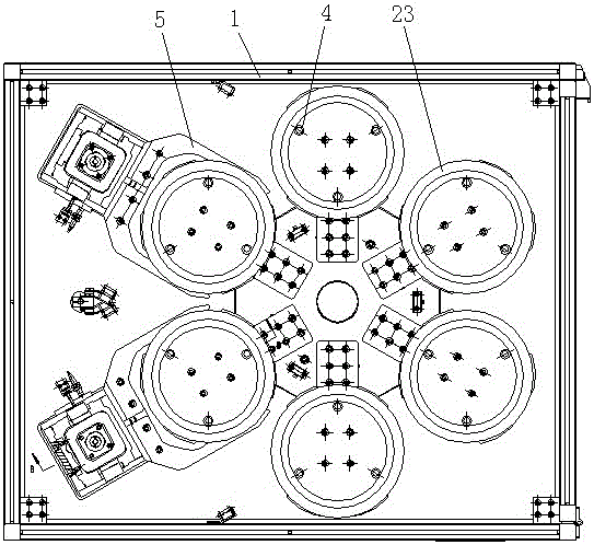
[0032] The workpiece horizontal rotary transport mechanism includes a first motor 2 arranged on the bin frame 1, a turntable 3 connected to the rotor of the first motor, and a workpiece loading mechanism 4 arranged at equal intervals along the circumferential direction of the turntable;

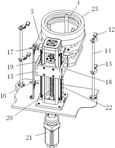
[0033] There are two sets of the workpiece lifting mechanism, and the two sets of workpiece lifting mechanisms are arranged correspondingly to the two sets of workpiece loading mechanisms 4. The workpiece lifting mechanism includes a jaw 5 for transporting the workpiece on the workpiece loading mechanism and a driving device for driving the jaw 5 to lift .

[0034] In this embod...


PUM


Abstract

The invention discloses an accurate positioning storage bin. The accurate positioning storage bin comprises a storage bin frame, workpiece lifting mechanisms and a workpiece horizontal rotary conveying mechanism; the workpiece horizontal rotary conveying mechanism comprises a first motor which is arranged on the storage bin frame, a rotary disc which is connected with a first motor rotor and workpiece loading mechanisms which are arranged along the peripheral direction of the rotary disc at equal intervals; and two sets of workpiece lifting mechanisms are arranged and are distributed opposite to the two sets of workpiece loading mechanisms, and each workpiece lifting mechanism comprises a clamping jaw for conveying workpieces on the workpiece loading mechanisms and a drive device for driving the clamping jaw to lift and descend. According to the accurate positioning storage bin, the first motor drives the rotary disc so as to drive the workpiece loading mechanisms to rotate horizontally, so that the transmission error existing in conventional storage bin chain wheel and chain transmission is eliminated, the repeat positioning precision along the horizontal direction is high, and a manipulator of processing equipment can accurately take and store materials; and moreover, a plurality of workpiece loading mechanisms can be arranged on the same rotary disc, the loading capacity of the storage bin is large and the storage bin occupies a small area.

Description

technical field [0001] The invention relates to a mechanical device, in particular to a workpiece loading, conveying and positioning device. Background technique [0002] At present, the traditional and common silos include flat friction plate silos and multi-station silos. [0003] The plane friction plate type silo uses a motor to drive the sprocket, and the sprocket drives the friction plate chain to realize the horizontal transportation of the workpiece. Together to achieve vertical transport. At the same time, the workpiece is positioned on the working line by the sensor. [0004] The traditional multi-station silo also uses the motor to drive the sprocket, the sprocket drives the chain, and the chain drives the workpiece pallet fixed on it to realize the horizontal transportation of the workpiece. After the workpiece is transported to the machine tool or the material grabbing point of the manipulator, A motor drives the supporting rod to lift the workpiece to realiz...

Claims


Application Information

Patent Timeline
Patent Type & Authority Patents(China)
IPC IPC(8): B23Q7/00
Inventor 李博陈鹏李先广李红刘宇李蒙
Owner CHONGQING MACHINE TOOL GROUP
Learn More