
Vehicle

A vehicle and control unit technology, applied in the field of vehicles, can solve problems such as vehicle enlargement, achieve the effects of suppressing enlargement, reducing configuration space, and suppressing voltage drop

Active Publication Date: 2015-06-17
HONDA MOTOR CO LTD
View PDF6 Cites 0 Cited by
  • Summary
  • Abstract
  • Description
  • Claims
  • Application Information

AI Technical Summary

Problems solved by technology

[0008] Therefore, it is conceivable to increase the size of the rotating electrical machine or the battery to compensate for the decrease in the drive torque or the decrease in the efficiency of charging the battery.
In addition, it is also considered to install the control unit on or behind the crankcase of the power unit, that is, the engine. However, as far as the components of the intake system or the combined swing engine are concerned, it is necessary to take care of the interference with the rear wheels, etc., which will cause vehicle damage. Large-scale

Method used


Image

  • Vehicle
  • Vehicle
  • Vehicle

Examples


no. 1 approach )

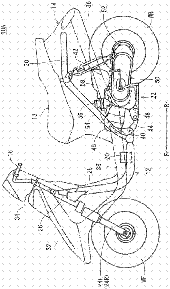
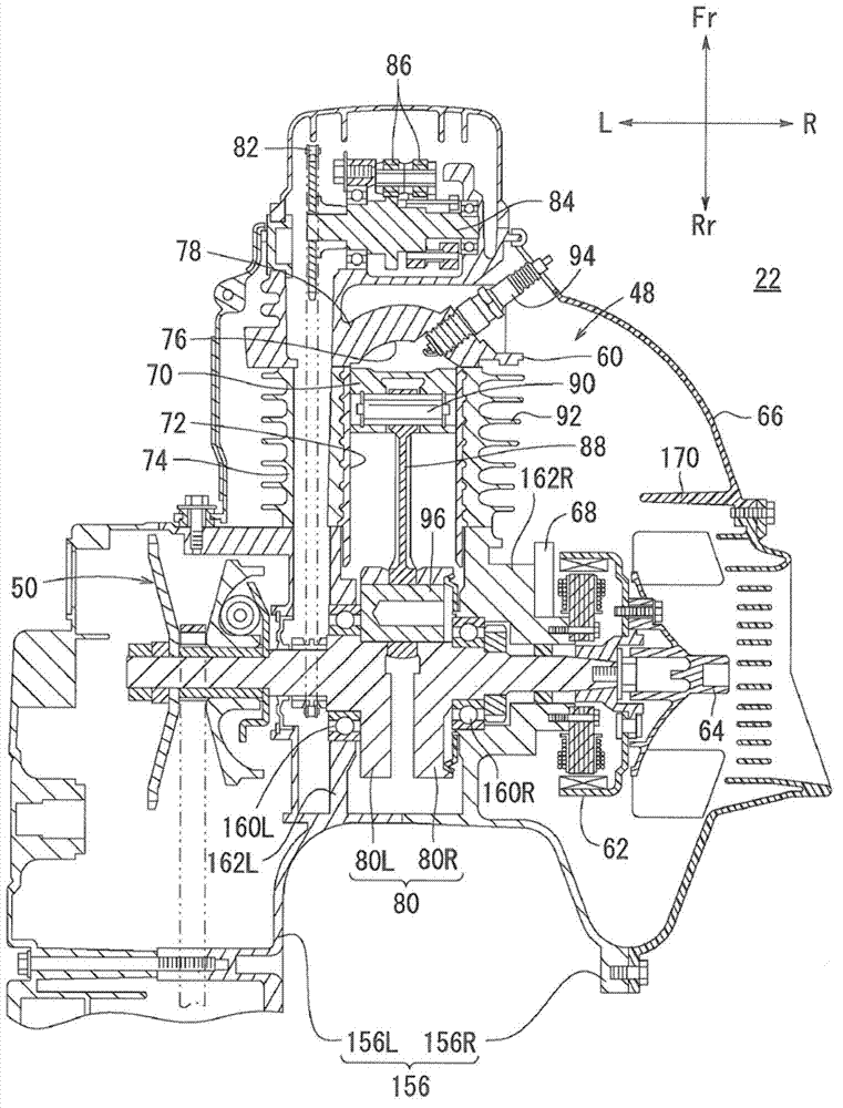
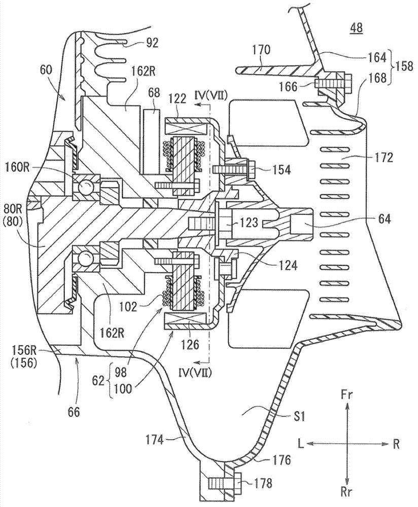
[0091] First, refer to Figure 1 to Figure 15 A motorcycle 10A of the first embodiment will be described. exist figure 1 In FIG. 2 , for convenience of description, the body cover 14 is shown by a phantom line (two-dot chain line). In addition, in the two-wheeled motor vehicle 10A, for mechanisms or components that are provided symmetrically one on each left and right sides of the vehicle body, "L" is assigned to the left reference numeral, and "R" is assigned to the right reference numeral. .

[0092] Such as figure 1 As shown, a two-wheeled motor vehicle 10A includes a frame 12 constituting a vehicle body, a body cover 14 covering the frame 12, front wheels WF that are steerable wheels, handlebars 16 that steer the front wheels WF, rear wheels WR that are drive wheels, and a steering wheel. The vehicle seat 18, storage battery 20 and swing unit 22 that the staff sits on.

[0093] The vehicle frame 12 has a pair of left and right front forks 24L, 24R pivotally supporting...

no. 2 approach )

[0179] Below, refer to Figure 16 and Figure 17 A motorcycle 10B according to a second embodiment of the present invention will be described. In the motorcycle 10B of this embodiment, the air-cooled engine 48 is replaced with a water-cooled engine 260 .

[0180] That is, if Figure 16 As shown, a water jacket 266 through which cooling water (refrigerant) flows is formed on a cylinder block 262 and a cylinder head 264 constituting the engine 260 . Also, the plurality of cooling fins 92 formed on the cylinder block 74 of the first embodiment are not provided.

[0181] The engine 260 has a heat exchanger portion 268 for exchanging heat (cooling) with the cooling water flowing through the water jacket 266 . The heat exchanger unit 268 is arranged on the right side of the blower 64 .

[0182] A cover member 270 constituting the engine 260 is provided with a cover 272 instead of the cover 158 of the first embodiment. The shroud 272 is configured to surround the rotary electri...


PUM


Abstract

The invention provides a vehicle which controls accommodation space of wires into a minimum limit by shortening the length between a plurality of coils forming a rotary motor stator and a control unit, and allows the control unit to be compactly mounted on an engine. A two-wheeled motor vehicle (10A) is provided with a swinging unit (22) which is disposed on a vehicle frame (12) and comprises an engine (48). The engine (48) comprises a rotary motor (62) which comprises a stator (98) and an outer rotor (100) comprising a plurality of coils (110); a storage battery (20) electrically connected with the plurality of coils (110); a crankshaft (80) rotatably connected with the outer rotor (100) for rotation; and a control unit (68) which controls power current by switching on and off the connection of the plurality of coils (110) with the storage battery (20), and thus allows the rotary motor (62) to act as a motor or a generator. The control unit (68) is disposed near the rotary motor (62).

Description

technical field [0001] The invention relates to a vehicle having a rotating electric machine electrically connected to a battery. Background technique [0002] Conventionally, a two-wheeled motor vehicle including a rotating electric machine called an ACG starter motor, which functions as a motor and a generator, is widely known. [0003] Such a two-wheeled motor vehicle generally includes a control unit that switches connections between a plurality of coils constituting a stator of a rotating electric machine and a battery to control energization current. [0004] Patent Document 1 proposes a two-wheeled motor vehicle in which a rotary electric machine is provided at one end of a crankshaft of a combined swing engine, and a control unit is provided near a head pipe that pivotally supports a handlebar. [0005] Patent Document 1: (Japanese) Unexamined Patent Application Publication No. 2010-223135 [0006] In the two-wheeled vehicle described in Patent Document 1, the cont...

Claims


Application Information

Patent Timeline
Patent Type & Authority Patents(China)
IPC IPC(8): F02N11/08F02D29/06H02K11/00B62K11/00B62J99/00
Inventor 柳泽毅扇谷宽一郎
Owner HONDA MOTOR CO LTD
Learn More