
Measuring device for brillouin optical sensing type continuous multipoint displacement meter

A technology of measuring devices and displacement meters, which is applied in the direction of measuring devices, optical devices, instruments, etc., can solve the problems of only measuring 4 to 5 points, difficulty in construction, increased cost, and insufficient judgment of accurate positions, etc., to achieve Excellent performance, reliability advantages, and simple structure

Active Publication Date: 2013-04-10
POWERCHINA HUADONG ENG COPORATION LTD
View PDF5 Cites 7 Cited by
  • Summary
  • Abstract
  • Description
  • Claims
  • Application Information

AI Technical Summary

Problems solved by technology

The current testing instruments and methods have four problems in use: First, limited by the number of sensors, usually only the displacement of 4 to 5 points can be measured at most, which is not enough to judge the exact location of the actual deformation; It needs a transmission rod several meters or even tens of meters long to transmit the axial deformation of the deep part to the orifice. Problems such as thermal expansion and contraction of the transmission rod itself, distortion, and stability of the pressure rod may cause distortion of the measured value; three. In the conversion of relative displacement to absolute displacement, the measured value of the deepest point should be used as the benchmark. Once this measuring point fails, other measuring points cannot be calculated. If there are many, the required drilling diameter will be larger, and the construction difficulty and cost will increase.

Method used


Image

  • Measuring device for brillouin optical sensing type continuous multipoint displacement meter
  • Measuring device for brillouin optical sensing type continuous multipoint displacement meter
  • Measuring device for brillouin optical sensing type continuous multipoint displacement meter

Examples


Embodiment Construction

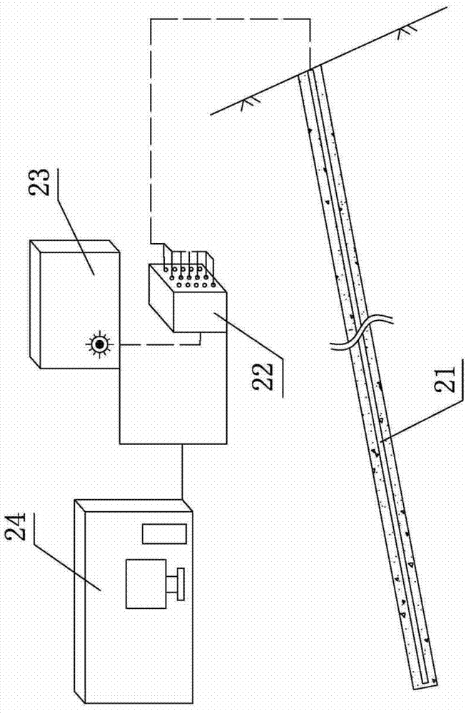
[0027] Such as figure 1 As shown, the present embodiment includes a Brillouin light-sensing continuous multi-point displacement meter 21, an optical switch 22 and a Brillouin demodulator 23 connected in turn to the displacement meter through a transmission optical cable, and the demodulator 23 through a signal line. The data analysis computer 24 connected to the instrument; wherein the Brillouin optical sensor continuous multi-point displacement meter 21 is installed in the borehole, and is closed and consolidated by grouting; the optical switch 22 is used to switch the measurement line; the data analysis computer 24 passes The signal line is connected to the optical switch 22 . Its working principle is: the optical signal detected by the Brillouin optical sensor continuous multi-point displacement meter 21 is led to the Brillouin demodulator 23 through the optical transmission cable through the optical switch 22, and the measurement results are uploaded to the data analysis c...


PUM

PropertyMeasurementUnit
Outer diameteraaaaaaaaaa

Abstract

The invention relates to a measuring device for a brillouin optical sensing type continuous multipoint displacement meter. The invention aims at providing the measuring device for the brillouin optical sensing type continuous multipoint displacement meter to simplify the whole structure, reduce construction difficulty and cost and accurately justify the occurrence location of an actual transformation. The technical schemes includes that the measuring device for the brillouin optical sensing type continuous multipoint displacement meter is characterized by comprising a brillouin optical sensing type continuous multipoint displacement meter which is solidified in a drill hole through grouting, a brillouin interrogator which is connected with the displacement meter through a transmission optical cable and a data analysis computer which is connected with the interrogator through signal lines. The measuring device for the brillouin optical sensing type continuous multipoint displacement meter is suitable for the safety monitoring fields of water conservancy,hydropower and geological engineering.

Description

technical field [0001] The invention relates to a detection device for deep displacement of rock and soil based on Brillouin distributed optical fiber sensing technology, especially a Brillouin optical sensing continuous multi-point displacement meter measurement device, which is mainly suitable for water conservancy and hydropower and The field of geological engineering safety monitoring. Background technique [0002] During the excavation of slopes, underground caverns and the construction of large-scale foundation projects, sensors such as bedrock displacement meters and multi-point displacement meters are generally used to monitor the deep displacement of rock and soil. For transmission rods of different lengths, the displacement of the anchorage end relative to the orifice at different depths is measured, and the deformation of each measuring point and the orifice is converted through the assumed deep fixed point. The sensors used are classified according to the sensin...

Claims


Application Information

Patent Timeline
IPC IPC(8): G01B11/02G01B11/16
Inventor 崔何亮王玉洁朱锦杰
Owner POWERCHINA HUADONG ENG COPORATION LTD
Learn More