Device and mass spectrometry for direct electrospray ionization of sample on microfluidic chip

A microfluidic chip and electrospray ionization technology are applied in the direction of material analysis, measurement device, and material analysis by electromagnetic means, achieving the effect of low cost and simple operation.

Inactive Publication Date: 2013-04-10
FUDAN UNIV
View PDF8 Cites 5 Cited by
  • Summary
  • Abstract
  • Description
  • Claims
  • Application Information

AI Technical Summary

Problems solved by technology

[0005] In view of the shortcomings of the prior art described above, the object of the present invention is to provide a device and method for direct electrospray ionization of samples on a microfluidic chip, to solve the problem of existing microfluidic devices in mass spectrometry. existing problems

Method used


Image

  • Device and mass spectrometry for direct electrospray ionization of sample on microfluidic chip
  • Device and mass spectrometry for direct electrospray ionization of sample on microfluidic chip
  • Device and mass spectrometry for direct electrospray ionization of sample on microfluidic chip

Examples


Embodiment 1

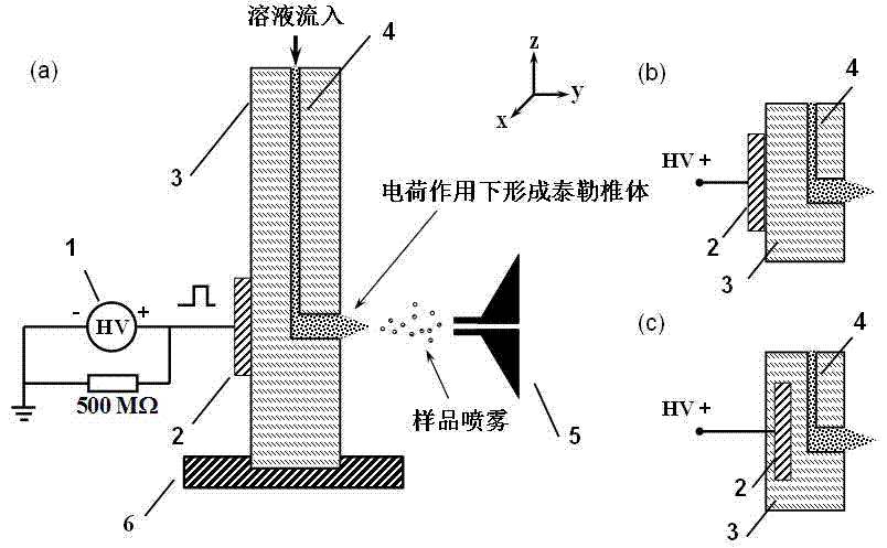
[0036] Such as figure 1 As shown, the microfluidic chip 3 is fixed on its three-dimensional adjustment platform 6 . Adjust the three-dimensional adjustment platform so that the outlet of the microchannel 4 is located 5-10 mm in front of the inlet of the mass spectrometer 5, so that ionization can be better during ionization. Pass the liquid to be tested into the sample microchannel 4, and deliver the liquid to the outlet of the microchannel. Turn on the pulse power supply 1, output pulsed DC high-voltage electrical signals to the plate 2, the output frequency is 1 Hz ~ 10 kHz, and the output voltage is 3 ~ 15 kV. The specific output frequency and output voltage need to be determined according to the type of sample to be analyzed and Specific adjustments such as flow rate.

[0037] When the power supply 1 is at the rising edge of the pulse output, the solution will form an electric double layer due to charging (negative charges are gathered near the electrode, and positive ch...

Embodiment 2

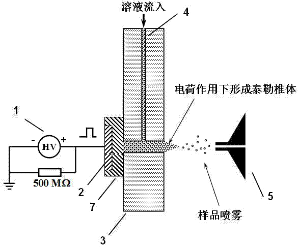
[0040] This embodiment is similar to the device of embodiment 1, except that the design of the outlet of the microchannel of the microfluidic chip used in combination is different from that shown in example 1. Such as figure 2 As shown, the sample micro pool at the outlet of the micro channel has openings on the upper and lower sides of the chip. At this time, an insulating layer 7 (with a thickness of 0.5 mm to 2 mm) needs to be coated on the surface of the electrode 2 . The electrode 2 covered with the insulating layer 7 is placed at one end of the outlet of the microchannel, and the other end is directed to the mass spectrometry inlet. As described in Example 1, after the sample flows into the sample microcell through the sample microchannel 4, under the action of the pulsed high voltage output by the power supply 2, sample ions are generated for detection by the mass spectrometer 5.

Embodiment 3

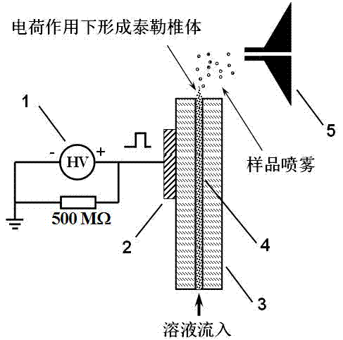
[0042] This embodiment is similar to the device of embodiment 1, except that the design of the outlet of the microchannel of the microfluidic chip used in combination is different from that shown in example 1. The outlet of the sample microchannel 4 does not adopt the design of the sample microcell, and the sample flows out directly in the microchannel. At this time, if image 3 As shown, the electrode 2 needs to be placed on the side of the chip near the outlet of the sample microchannel 4 . As described in Example 1, after the sample flows through the sample microchannel 4 to the outlet of the channel, under the action of the pulsed high voltage output by the power supply 2 , sample ions are generated for detection by the mass spectrometer 5 .


PUM


Abstract

The invention belongs to the technical field of microfluidic chips, and particularly relates to a device and a mass spectrometry for direct electrospray ionization of a sample on a microfluidic chip. The device at least comprises a three-dimensional operating platform for placing the microfluidic chip, an electrode for providing spray voltage, a pulsed high-voltage power supply, and a mass spectrum arranged beside an ionization device, wherein the electrode for providing the spray voltage is not directly contacted with liquid in the microfluidic chip. A spray needle is not required to be fabricated or connected on the microfluidic chip, or the original design of a chip microchannel is not required to be changed, and a solution sample in the chip microchannel can be directly ionized by utilizing charge and discharge processes of pulsed voltage, and then the mass spectrometry can be conducted. In addition, a high-voltage in the device is not directly contacted with a solution, and the original function of the microfluidic chip is not affected due to chemical reaction on the electrode. The device is simple and convenient to operate, and is suitable for direct ionization and the mass spectrometry of the sample on the microfluidic chip.

Description

technical field [0001] The invention belongs to the technical field of microfluidic chips, and in particular relates to a device and a mass spectrometry analysis method that can be used for direct electrospray ionization of samples on a microfluidic chip. Background technique [0002] Microfluidic chip analysis is based on the chip as the operating platform, based on analytical chemistry, supported by micro-electromechanical processing technology, and characterized by micro-pipeline network. The goal is to integrate the functions of the entire laboratory, including sampling, dilution, Reagents, reactions, separations, detections, etc. are integrated on the microchip and can be used multiple times. Microfluidic chip analysis technology has the characteristics of controllable liquid flow, minimal consumption of samples and reagents, and fast analysis speed. It can analyze hundreds of samples at the same time in a few minutes or even less, and it can be realized online. The wh...

Claims


Application Information

Patent Timeline
Patent Type & Authority Applications(China)
IPC IPC(8): G01N27/68
Inventor 贾滨聂磊徐国宾杨芃原
Owner FUDAN UNIV
Why Eureka
Try Eureka