Acoustical emitting and resistivity joint monitoring device and monitoring method of fracture process of rock specimen
A technology of joint monitoring and resistivity, applied in measurement devices, material analysis using acoustic wave emission technology, measurement of resistance/reactance/impedance, etc. The effect of improving test efficiency
- Summary
- Abstract
- Description
- Claims
- Application Information
AI Technical Summary
Problems solved by technology
Method used
Image
Examples
Embodiment 1
[0059] Embodiment 1 uses the acoustic-electric integrated test probe described in embodiment 2 and the acoustic-electric integrated test probe clamping device 14 described in embodiment 3 to use a combined real-time monitoring device for acoustic emission and resistivity.
[0060] Example 1
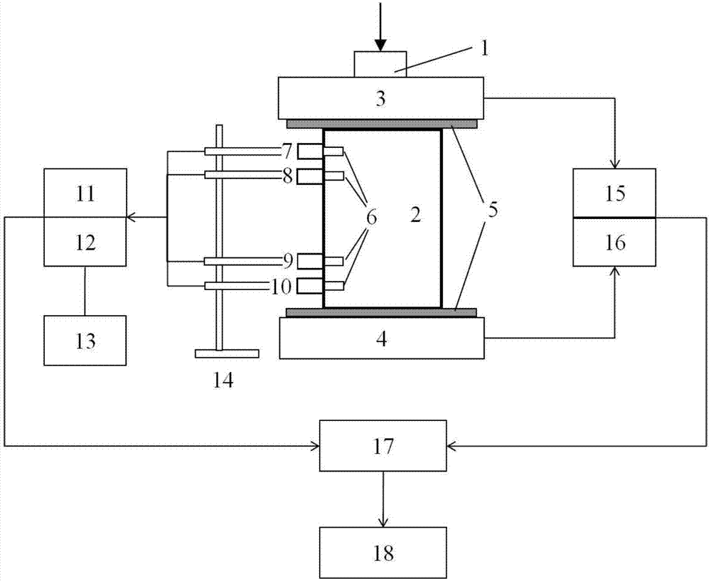
[0061] Such as Figure 1-Figure 7 As shown, on the rigid servo press 1, a rock sample 2 is placed. The rock sample 2 is a conventional cylindrical standard specimen with a size of Ф50mm×100mm, which conforms to the "GB / T50266-99 Engineering Rock Mass Test Method Standard" requirements. A layer of plastic film 5 coated with insulating varnish is pasted between the rock sample 2 and the upper pressure plate 3 and the lower pressure plate 4 to prevent the current from being directly conducted through the rigid servo press 1 during the resistivity measurement process.
[0062] The resistivity measurement of the rock sample 2 adopts the quadrupole method, so it is necessary to arrange four b...
Embodiment 2
[0079] Embodiment 2 An acoustic and electric integrated test probe
[0080] Such as Figure 4 As shown, the outermost layer of an acoustic-electric integrated test probe is a shell 24 made of metal. On the one hand, it can increase the strength of the probe, and on the other hand, it can also shield the external high-frequency signals to prevent the acoustic emission signal from being disturbed. . Acoustic emission signal collection is realized by the piezoelectric element 20. The front end of the piezoelectric element 20 is designed in an arc shape, which can better contact with the surface of the cylinder standard rock sample 2 to facilitate acoustic emission coupling. In addition, the piezoelectric element 20 is made into a hollow cylinder, and electrode 19 stretches out from the hole in the middle. The part of the electrode 19 protruding from the housing 24 is about 8mm long, and it can just extend into the borehole 6 during the test, and the arc surface of the front end...
Embodiment 3
[0082] Embodiment 3 An acoustic-electric integrated test probe clamping device
[0083] Such as Figure 5 As shown, an acoustic-electric integrated test probe clamping device 14 is composed of a probe clamp 28 , a rotating mechanism 29 , a slide bar 30 , a main pole 31 , a hinge 32 and a base 33 . The base 33 supports the whole device and is connected with the main pole 31 . In actual use, a plurality of rotating mechanisms 29 may be installed on the main pole 31 as required, together with a slide bar 30 and a probe clamp 28, so as to realize simultaneous clamping of multiple probes.
[0084] The main pole 31 is divided into upper and lower sections again, the lower section is welded into one body with the base 33 , and the upper and lower sections are connected by a hinge 32 . The structure of the hinge 32 is as Figure 6 As shown, there are thin blocks wedging between the upper and lower sections of the main pole 31, and the thin blocks are penetrated by screws, and the t...
PUM
 Abstract
Description
Claims
Application Information
 - R&D
- Intellectual Property
- Life Sciences
- Materials
- Tech Scout
- Unparalleled Data Quality
- Higher Quality Content
- 60% Fewer Hallucinations
Browse by: Latest US Patents, China's latest patents, Technical Efficacy Thesaurus, Application Domain, Technology Topic, Popular Technical Reports.
© 2025 PatSnap. All rights reserved.Legal|Privacy policy|Modern Slavery Act Transparency Statement|Sitemap|About US| Contact US: help@patsnap.com


