Current source type bidirectional multipulse converter based on polarity-variable direct current bus

A technology of bidirectional converter and DC bus, applied in the direction of conversion equipment with reversible, can solve the problem that energy cannot be transmitted in both directions, and achieve simple control loop and filter design, volume reduction, and volume reduction. Effect

Inactive Publication Date: 2013-04-10
NANJING UNIV OF AERONAUTICS & ASTRONAUTICS
View PDF7 Cites 6 Cited by
  • Summary
  • Abstract
  • Description
  • Claims
  • Application Information

AI Technical Summary

Problems solved by technology

[0006] The purpose of the present invention is to reduce the volume and weight of its magnetic components on the basis of the advantages of simple control and filtering of the traditional current source type multi-pulse inverter, to overcome the shortcoming that its energy cannot be transmitted bidirectionally, and to propose a bidirectional switch tube-based current Source Bidirectional Multi-Pulse Converter

Method used


Image

  • Current source type bidirectional multipulse converter based on polarity-variable direct current bus
  • Current source type bidirectional multipulse converter based on polarity-variable direct current bus
  • Current source type bidirectional multipulse converter based on polarity-variable direct current bus

Examples


Embodiment 1

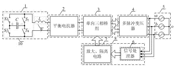
[0037] attached figure 1 A schematic structural diagram of the current source bidirectional multi-pulse converter based on the variable polarity DC bus of the present invention is given, including a DC side circuit (1), a reversible three-phase bridge group (3), a multi-pulse transformer (4), A three-phase AC power supply (5) and a control circuit (8). When the system is a 12- or 24-pulse bidirectional converter, it is better to connect a balance reactor (2) between the DC side circuit (1) and the reversible three-phase bridge group (3) to realize the current sharing of each three-phase bridge. The DC side circuit (1) is composed of a filter inductor (9) and a polarity-selectable DC bus circuit (10). The optional polarity DC bus circuit (10) is composed of switching tubes with double-quadrant voltage and single-quadrant current or composite switching tubes to form a single-phase bridge, and the two ends of the DC load are respectively connected to the midpoint of the two brid...

Embodiment 2

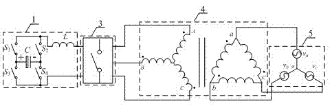
[0040] Such as image 3 As shown, the structure schematic diagram of the isolated 6-pulse bidirectional converter in the present invention. In this structure, no balance reactor (2) is connected between the DC side circuit (1) and the unidirectional three-phase bridge group (3), and the two ends of each three-phase bridge are connected to the same polarity terminals, and then connected to the two ends of the DC side circuit , the midpoints of each bridge arm are sequentially connected to the corresponding interface of the multi-pulse transformer.

[0041]

Embodiment 3

[0043] Such as Figure 4 As shown, the self-coupling type 12-pulse bidirectional converter structure of the present invention.


PUM


Abstract

The invention provides a current source type bidirectional multipulse converter based on a polarity-variable direct current bus, which comprises a direct current side circuit (1), a three-phase alternating current power supply (5), a one-way three-phase bridge set (3), a multipulse transformer (4) and a control circuit (8), wherein the direct current side circuit (1), the one-way three-phase bridge set (3), the multipulse transformer (4) and the three-phase alternating current power supply (5) are sequentially connected with one another; the signal input end of the control circuit (8) is connected between the multipulse transformer (4) and the three-phase alternating current power supply (5); and the control end of the control circuit (8) is connected with the one-way three-phase bridge set (3). The circuit topology, provided by the invention, can realize two-way energy flow of a current source type multipulse inverter, and directly controls current on the three-phase alternating current side; a controller and a filter are independent of each other; the converter has a simple design and high reliability, and is suitable for various locations needing the multipulse converter to realize two-way energy transmission.

Description

technical field [0001] The invention relates to a current source type bidirectional multi-pulse converter based on a variable polarity direct current bus, which belongs to the category of power electronic conversion. Background technique [0002] The multi-pulse inverter technology uses a phase-shifting transformer to superimpose the output of the multi-phase inverter to eliminate low-order harmonics and make the synthesized waveform approach to a sine wave. It has the advantages of less harmonic content, low switching frequency, high reliability, high efficiency, It has the advantages of strong overload capacity and no additional electromagnetic interference. At the same time, the phase-shifting transformer in the system can also electrically isolate the input and output, which has little pollution to the power grid. Based on the above characteristics, multi-pulse inverter technology is widely used in high-power AC drives, new energy applications and power quality control. ...

Claims


Application Information

Patent Timeline
Patent Type & Authority Applications(China)
IPC IPC(8): H02M7/72
Inventor 陈乾宏杨鸣强
Owner NANJING UNIV OF AERONAUTICS & ASTRONAUTICS
Why Eureka
Try Eureka