Integrated multi-mode imaging method fusing ultrasonic imaging, photoacoustic imaging and optical coherence tomography and system employing same

A technology of optical coherence tomography and multi-modal imaging, which is applied in the analysis of solids using sound waves/ultrasonic waves/infrasonic waves, material analysis using sound waves/ultrasonic waves/infrasonic waves, and scientific instruments, etc. In order to achieve the effects of reducing complexity and instability, improving portability and practicability, and improving operability and scope of application

Inactive Publication Date: 2013-04-17
JIANGXI SCI & TECH NORMAL UNIV
View PDF0 Cites 9 Cited by
  • Summary
  • Abstract
  • Description
  • Claims
  • Application Information

AI Technical Summary

Problems solved by technology

[0002] Single-mode imaging technology can only be imaged according to the change of a certain characteristic of the sample under test, and cannot obtain rich information and internal correlations of the sample in many ways, which has certain application limitations.
For example, Ultrasonic Imaging (USI) only reflects the acoustic impedance characteristics of the sample. It has the advantage of high penetration, but the imaging contrast is very low, and false reflections due to multiple reflections at the sample interface and side lobe interference are likely to cause errors. Judgment; Photoacoustic Imaging (PAI) only reflects the light absorption characteristics of the sample. It uses a broadband ultrasonic detector to detect ultrasonic waves instead of detecting scattered photons in pure optical imaging, effectively avoiding the strong scattering of light by the sample. Generally, a detection depth of 2-5 cm can be achieved, and the resolution can reach tens to hundreds of microns; Optical Coherence Tomography (OCT) only reflects the light scattering characteristics of the sample, but in general, the sample The change in the reflectivity of light is very small, and as the penetration depth of light increases, the strong scattering of light in the sample causes the spatial resolution of imaging to drop sharply, generally only reaching a detection depth of 1-5 mm, but The resolution can reach several microns to tens of microns

Method used


Image

  • Integrated multi-mode imaging method fusing ultrasonic imaging, photoacoustic imaging and optical coherence tomography and system employing same

Examples


Embodiment 1

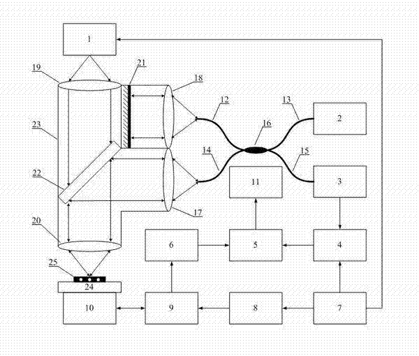
[0027] The structure of this embodiment is as figure 1 As shown, the names of each component are: 1. Laser diode, 2. Light emitting diode, 3. Photodetector, 4. Lock-in amplifier, 5. Computer, 6. Preprocessing circuit, 7. Sequence controller, 8. Pulse Voltage generator, 9. Switching circuit, 10. Ultrasonic sensor, 11. Three-dimensional translation stage, 12. One-way optical fiber, 13. Two-way optical fiber, 14. Three-way optical fiber, 15. Four-way optical fiber, 16. Optical fiber coupler, 17 , side lower lens, 18, side upper lens, 19, upper lens, 20, lower lens, 21, reflecting mirror, 22, dichroic mirror, 23, optical path housing, 24, sample stage, 25, sample.

[0028] Among them, the laser diode 1 uses the 905D4S12X model of Laser Components in the United States, and the pulse laser emitted by it has a wavelength of 905nm and a peak power of 140W; the light-emitting diode 2 uses the optical fiber output superluminescent light-emitting diode SLD-101 of Beijing Gaoguang Technol...


PUM


Abstract

The invention provides a portable multi-mode imaging method fusing photoacoustic imaging and optical coherence tomography and a system employing the same. The system consists of a laser diode, a drive power supply, a signal generator, a lock-in amplifier, a photoelectric detector, an optical fiber coupler, LEDs, a signal processor, a three-dimensional translation stage, optical fibers, a lens group, a reflector, a dichroic mirror, an optical path housing and a sample table, and can achieve independent optical coherence tomography or photoacoustic imaging and optical coherence tomography combined multi-mode imaging. According to the invention, a photoacoustic imaging system is miniaturized and combined with an optical coherence tomography system to form an integrated portable system so as to realize integration, miniaturization and practicability of two-mode imaging.

Description

technical field [0001] The present invention relates to a multi-modal imaging technology, in particular to an integrated multi-modal imaging method and system that integrates ultrasonic imaging, photoacoustic imaging and optical coherence tomography. Background technique [0002] Single-mode imaging technology can only image according to the change of a certain characteristic of the sample under test, and cannot obtain rich information and internal correlations of the sample in many ways, which has certain application limitations. For example, Ultrasonic Imaging (USI) only reflects the acoustic impedance characteristics of the sample. It has the advantage of high penetration, but the imaging contrast is very low, and false reflections due to multiple reflections at the sample interface and side lobe interference are likely to cause errors. Judgment; Photoacoustic Imaging (PAI) only reflects the light absorption characteristics of the sample. It uses a broadband ultrasonic de...

Claims


Application Information

Patent Timeline
Patent Type & Authority Applications(China)
IPC IPC(8): G01N21/45G01N21/31G01N29/09G01N29/028
Inventor 曾吕明刘国栋杨迪武纪轩荣
Owner JIANGXI SCI & TECH NORMAL UNIV
Why Eureka
Try Eureka