Capacitive energy storage type rechargeable battery and charging device thereof
A capacitor energy storage type, rechargeable battery technology, applied in the field of daily necessities, can solve the problems of shortening the service life of Farad capacitors, increasing the cost and weight, and being difficult to operate.
- Summary
- Abstract
- Description
- Claims
- Application Information
AI Technical Summary
Problems solved by technology
Method used
Image
Examples
Embodiment 1
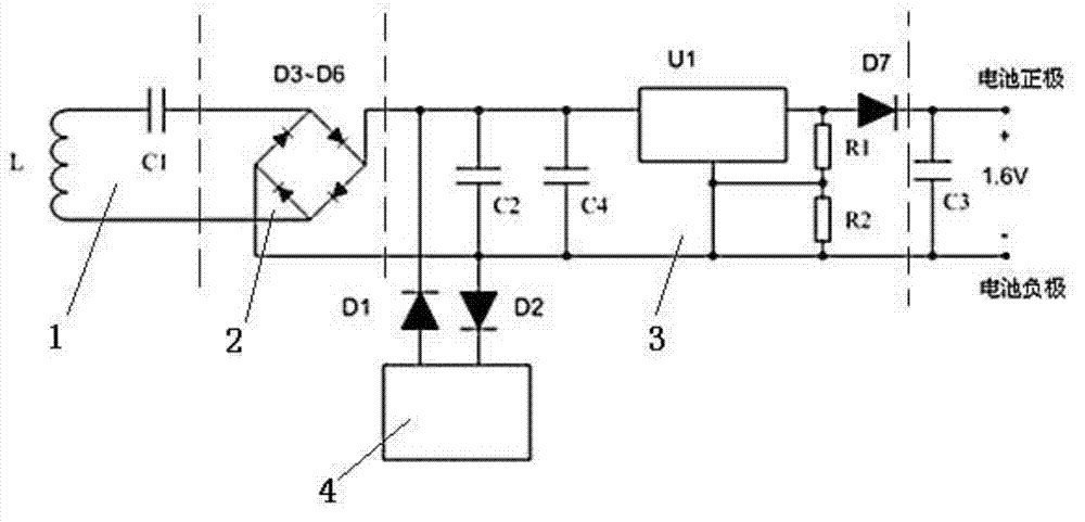
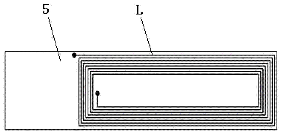
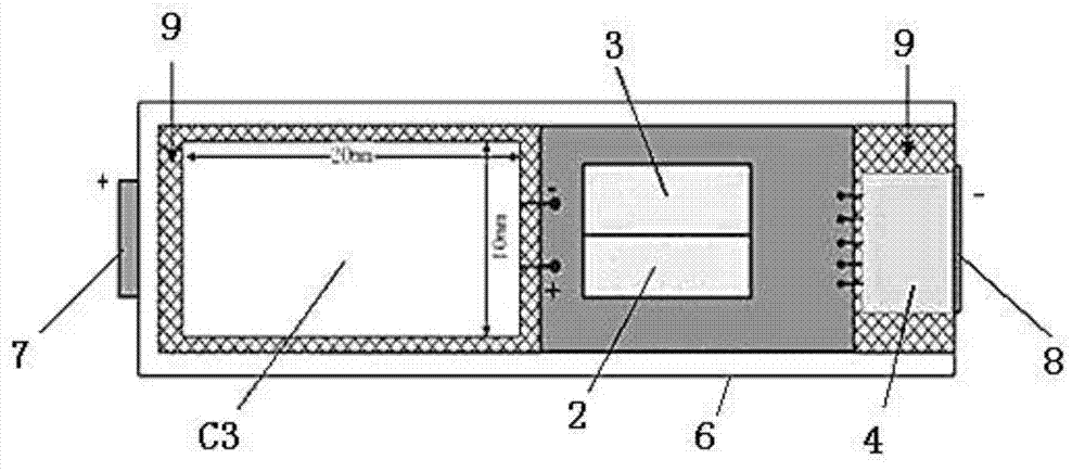
[0027] Such as figure 1 As shown, this embodiment includes: a resonant receiving circuit 1, a rectifying circuit 2, a step-down voltage stabilizing circuit 3 and an energy storage capacitor C3 composed of a series receiving coil L and a resonant capacitor C1 connected in sequence, wherein: the receiving coil L cooperates with the resonant The capacitor C1 senses and receives the electromagnetic energy sent by the wireless induction transmitting coil, and generates a stable 1.6V DC voltage through the rectifier circuit 2 and the step-down regulator circuit 3 for charging the energy storage capacitor C3.
[0028] In this example:
[0029] The rectification circuit 2 is a diode rectification circuit composed of four low-dropout diodes D3-D6, and the third to sixth diodes D3, D4, D5, and D6 are 1N5818 or similar low-dropout rectification diodes;
[0030] The step-down regulator circuit 3 includes: a DC regulator chip U1, a step-down circuit made up of resistors and diodes, and t...
Embodiment 2
[0048] Such as Image 6 As shown, this embodiment relates to a wireless charger for the above-mentioned battery, including: AC / DC power supply 10, control module 11, PWM driver 12, inverter half-bridge circuit 13, transmitting circuit 14, current detection resistor Rx and current Signal processing circuit 15, wherein: AC / DC power supply 10 receives 85V-264V AC input and outputs 5V and 18V direct current to the power supply end of control module 11 and inverter half-bridge circuit 13 respectively, and control module 11 outputs PWM signal to PWM driver 12 , the PWM driver 12 is connected to the input end of the inverter half-bridge circuit 13 and outputs the excitation current, the output end of the inverter half-bridge circuit 13 is connected to the transmitting circuit 13, and the feedback end of the inverter half-bridge circuit 13 is respectively connected to the current detection resistor Rx Connected to the current signal processing circuit 15, the output current of the tra...
PUM
| Property | Measurement | Unit |
|---|---|---|
| First resistor | aaaaa | aaaaa |
| Length | aaaaa | aaaaa |
| Width | aaaaa | aaaaa |
Abstract
Description
Claims
Application Information
 - R&D
- Intellectual Property
- Life Sciences
- Materials
- Tech Scout
- Unparalleled Data Quality
- Higher Quality Content
- 60% Fewer Hallucinations
Browse by: Latest US Patents, China's latest patents, Technical Efficacy Thesaurus, Application Domain, Technology Topic, Popular Technical Reports.
© 2025 PatSnap. All rights reserved.Legal|Privacy policy|Modern Slavery Act Transparency Statement|Sitemap|About US| Contact US: help@patsnap.com


