Mechanical defoaming device applied to stirred tank reactor

A mechanical defoaming and stirring reactor technology, applied in chemical/physical/physical-chemical stationary reactors, foam dispersion/prevention, etc., can solve problems such as complex structure, achieve convenient loading and unloading, improve defoaming efficiency, and eliminate foam Effect

Inactive Publication Date: 2013-04-24
JIANGNAN UNIV
View PDF8 Cites 8 Cited by
  • Summary
  • Abstract
  • Description
  • Claims
  • Application Information

AI Technical Summary

Problems solved by technology

The rotating vane type and centrifugal force type in the anti-foaming device outside the tank need additional power, and the structure is relatively complicated

Method used


Image

  • Mechanical defoaming device applied to stirred tank reactor
  • Mechanical defoaming device applied to stirred tank reactor

Examples


Embodiment 1

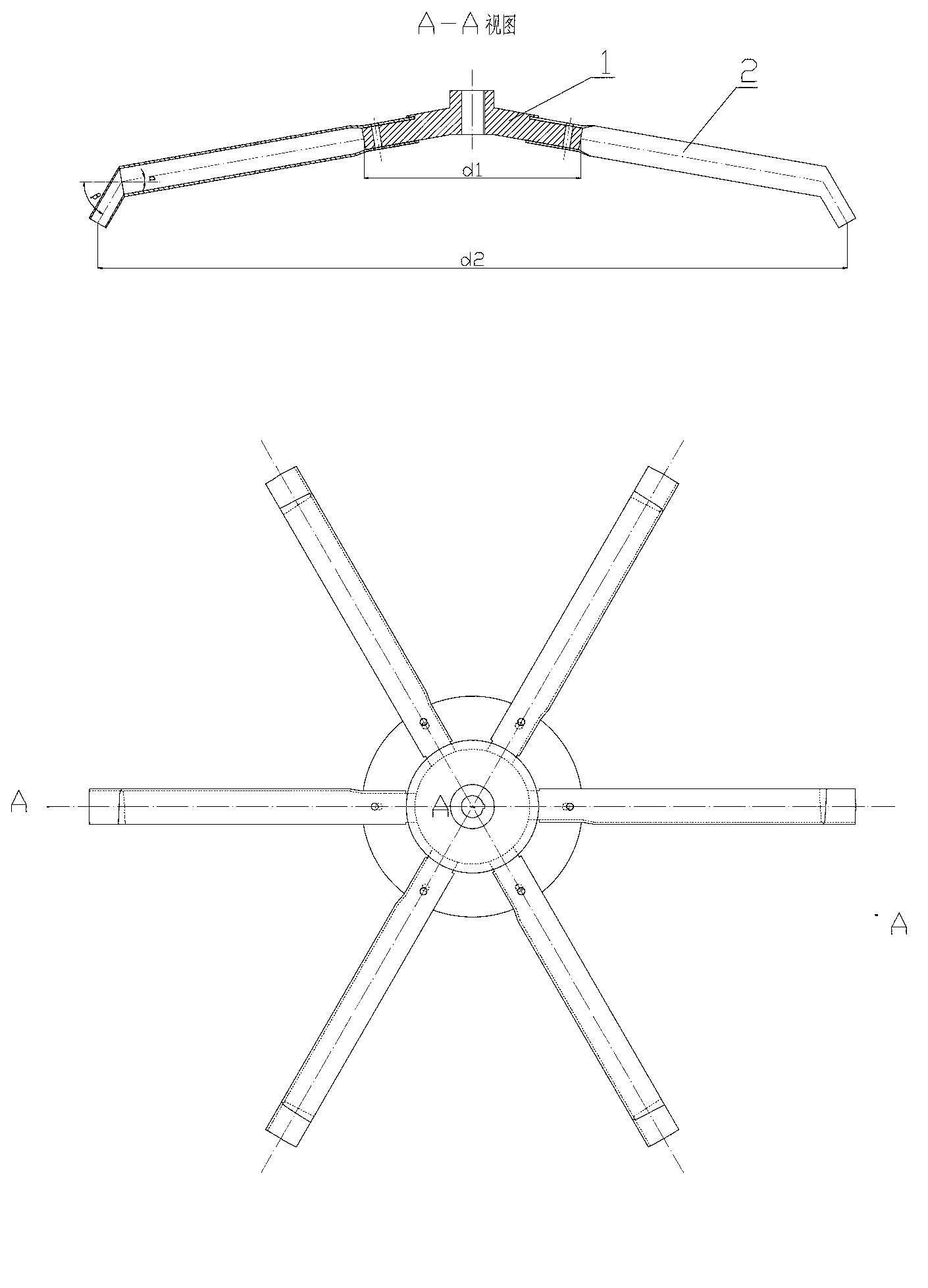
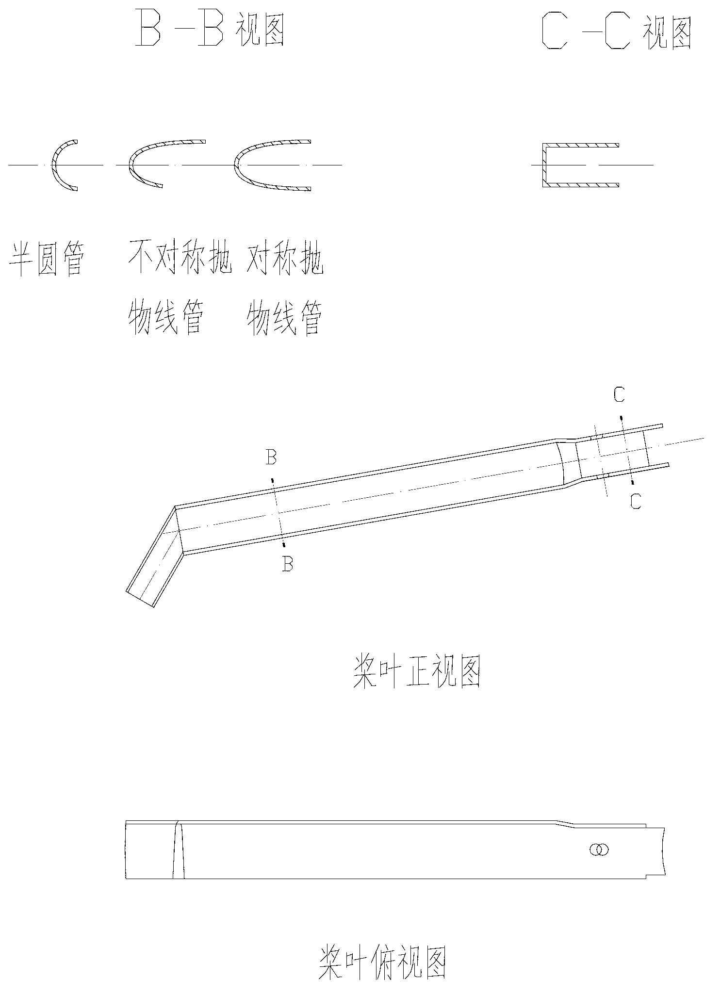
[0017] The mechanical defoaming device includes a hub 1 and paddles 2 . The central structure of the hub 1 is hollow cylindrical, the peripheral structure of the hub is truncated conical, the downward inclination angle α of the hub peripheral is 10o, and the diameter d1 of the hub is 1 / 5 of the kettle diameter. The section of the paddle 2 is an asymmetrical parabolic groove, and the paddle 2 is bent from an alloy thin plate. The diameter d2 of the paddle 2 is 3 / 5 of the diameter of the kettle, and the number of paddles is 6, which are arranged symmetrically on the hub. β is 60°. The mechanical defoaming device is installed on the stirring shaft in the stirred reactor and rotates together with the stirring shaft. The surfaces of the paddle 2 and the hub 1 are coated with a hydrophobic material, which is polytetrafluoroethylene.


PUM


Abstract

The invention discloses a mechanical defoaming device applied to a stirred tank reactor and belongs to the technical field of chemical machinery. The mechanical defoaming device comprises a hub and a paddle, wherein the center of the hub is a hollow cylinder; the periphery of the hub is provided with a cone frustum and has an included angle downwards; the section of the blade is a semicircular tube type groove, a symmetric parabolic groove or an asymmetric parabolic groove; 4-16 paddles are symmetrically arranged on the hub; the tail end of the paddle is provided with a downwards inclined liquid guide rail, so that the defoamed liquid is injected into the liquid level; the defoaming device is arranged on a stirring shaft in the tank and rotates along with the stirring shaft together; and the raising foam in the reaction kettle is captured by the paddle groove of the defoaming device and is pushed to the tail end of the paddle under the action of the centrifugal force. Because the hub and the paddle are downwards inclined, the foam facilitates the liquid film to discharge liquid in the motion process, and the film is compressed, sheared and crushed. A super-hydrophobic material is coated on the surface of the paddle, and the defoaming effect is improved. The paddle structure is simple, can be pressed and formed by the plates, can be manufactured into different specifications and sizes according to the requirements and is low in manufacturing cost.

Description

technical field [0001] The invention relates to a mechanical defoaming device applied to a stirred tank reactor. It can be used in chemical industry, food, fermentation, papermaking, textile and other fields. It belongs to the technical field of chemical machinery. Background technique [0002] Foam is often accompanied by industrial production processes, and many operations or processes often have a great impact on industrial production capacity due to the generation of foam. In the ventilated fermentation process of producing antibiotics, enzyme preparations, glutamic acid and microbial polysaccharides, liquid leakage often occurs due to foaming, which reduces the utilization rate of the fermentation tank, even affects oxygen supply, increases the risk of bacterial contamination, and makes the target product harvest. rate drops. Therefore, the efficient elimination of harmful foam has significant technical and economic significance, and the application of defoaming devi...

Claims


Application Information

Patent Timeline
Patent Type & Authority Applications(China)
IPC IPC(8): B01D19/02B01J19/18
Inventor 郑志永詹晓北朱莉蒋芸
Owner JIANGNAN UNIV
Why Eureka
Try Eureka