Spool component resistant to cavitation erosion and erosion wear for regulating valve

A wear adjustment and valve core assembly technology, applied in safety valves, balance valves, valve devices, etc., can solve the problems of short life of the regulating valve, aggravated valve core damage, pipeline erosion and wear, etc., to achieve uniform erosion and wear, reduce The effect of erosion wear and cavitation damage reduction

Inactive Publication Date: 2013-04-24
饶杰
View PDF9 Cites 7 Cited by
  • Summary
  • Abstract
  • Description
  • Claims
  • Application Information

AI Technical Summary

Problems solved by technology

[0007] (3) Optimize the valve seat and the solid valve core structure to reduce erosion and wear. When the transmission is under high pressure difference and negative pressure outlet conditions, the erosion and wear of the valve core’s throttling surface is inevitable, especially when the top of the valve core When there is a high-speed backflow impact of the medium, the top of the valve core will be damaged by both cavitation erosion and erosion wear. Even if the valve core is made of wear-resistant materials and a reasonable structure, the return velocity of the medium will increase with the damage of the top of the valve core. , it aggravates the damage of the spool, and the life of the regulating valve is still very short
[0008] (4) There is a certain bias flow in the regulating valve during the working process. When the valve outlet is negative pressure or close to negative pressure, severe cavitation will occur at the valve outlet, forming a gas-solid two-phase (little liquid phase) medium. High-speed transmission leads to severe erosion and wear of the pipeline behind the valve, which is obviously localized

Method used


Image

  • Spool component resistant to cavitation erosion and erosion wear for regulating valve
  • Spool component resistant to cavitation erosion and erosion wear for regulating valve
  • Spool component resistant to cavitation erosion and erosion wear for regulating valve

Examples


Embodiment Construction

[0024] The embodiments of the present invention will be further described below in conjunction with the drawings.

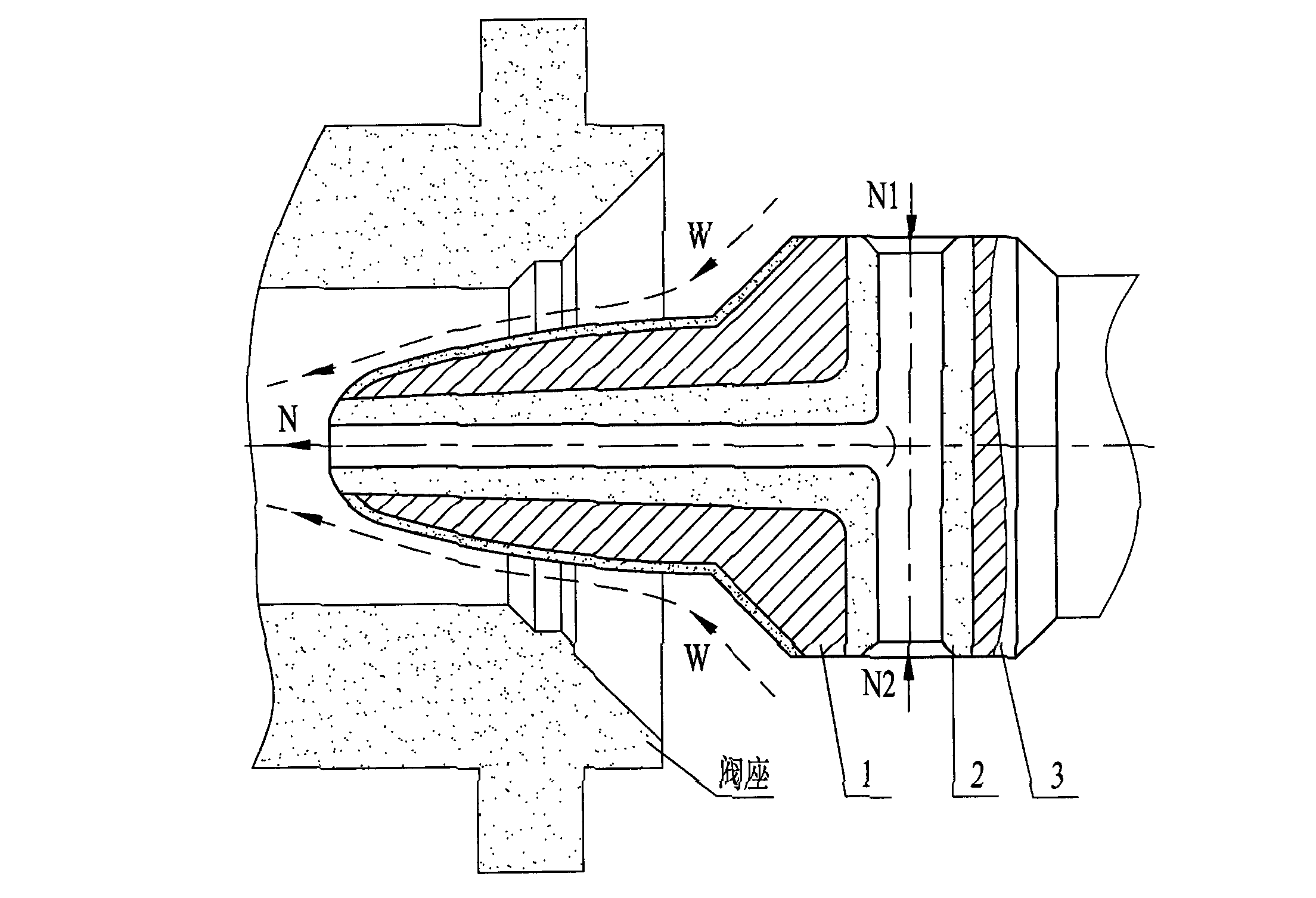
[0025] Such as figure 1 As shown, the valve core assembly of the present invention includes a valve core head 1, a valve core built-in throttle 2 and a valve core tail 3; the horizontal section of the valve core built-in throttle 2 is inserted into the central hole of the valve core head 1. The vertical section of the built-in throttle of the valve core is embedded in the hole formed by the connection between the valve core head 1 and the valve core tail 3. The connection described in this embodiment is welding, so that the regulating valve is formed during operation. There are two transmission passages between the head surface of the valve core and the valve seat, and in the internal throttle 2 of the valve core.

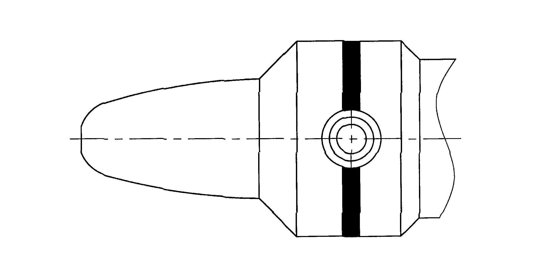
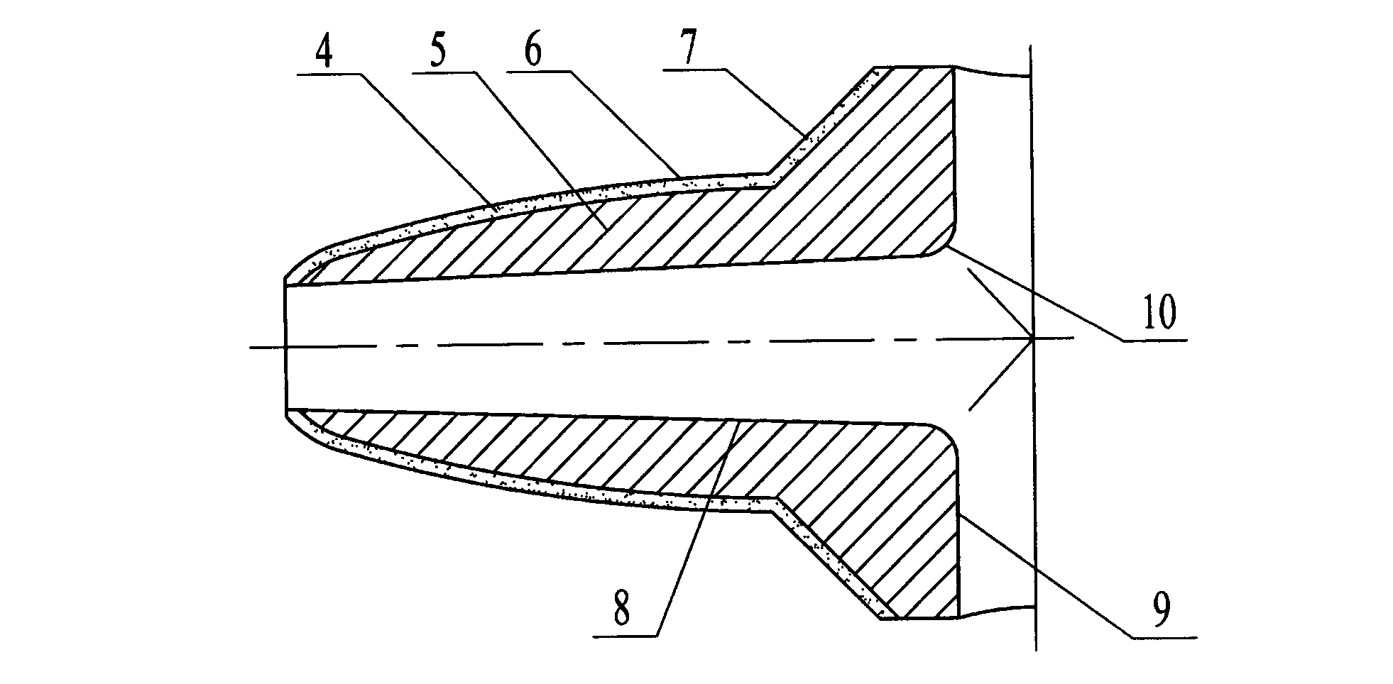
[0026] Such as figure 2 with image 3 As shown, the valve core head 1 includes a valve core surface layer 4 and a valve core head base body 5. The valve ...


PUM


Abstract

The invention discloses a spool component resistant to cavitation erosion and erosion wear for a regulating valve. The spool component comprises a spool head, a spool internal throttling element and a spool tail. A horizontal section of the spool internal throttling element is inserted into a central hole of the spool head, and a vertical section of the spool internal throttling element is embedded to a hole formed by connection of the spool head with the spool tail. The spool component forms split-flow transmission of media from two flow passages inside and outside a spool through the spool internal throttling element, so that cavitation erosion and erosion wear damage of the spool can be reduced greatly; and the regulating valve adopting the spool component is better in symmetry of downstream flowing distribution, downstream pipeline erosion wear rate can be decreased, the size of the regulating valve is decreased on the same transmission conditions, and the spool component is applicable to transmission working conditions such as solid containing, high pressure difference, negative pressure outlets and the like and is simple in structure and easy to popularize.

Description

Technical field [0001] The invention relates to a cavitation and erosion-resistant valve core assembly, in particular to the adjustment of high-speed transmission of liquid-solid two-phase or gas-liquid-solid three-phase media under high pressure difference and negative pressure outlet conditions The spool assembly used by the valve. Background technique [0002] Regulating valve, also known as control valve, is a device that is operated by power in a process control system to adjust fluid flow. It is used to adjust the flow medium to compensate for load disturbances, so that the controlled process variables (pressure, flow, liquid level, etc.) are as close as possible to the required set point. It is an important part of the industrial process control system and is widely used in coal Chemical, petrochemical, metallurgy, power generation and other fields. [0003] The angle valve is the angle valve. Compared with other types of control valves, it has better resistance to erosion...

Claims


Application Information

Patent Timeline
Patent Type & Authority Applications(China)
IPC IPC(8): F16K17/20
Inventor 饶杰
Owner 饶杰
Why Eureka
Try Eureka