
Filter drive circuit of swept source

A technology for driving circuits and filtering circuits, applied in circuits, lasers, laser components, etc., can solve problems such as insufficient output waveform frequency, low output current power, and inability to stably drive and operate filter drivers, etc., to achieve wavelength coordination and guarantee The effect of stability

Active Publication Date: 2013-04-24
LEPU MEDICAL TECH (BEIJING) CO LTD
View PDF4 Cites 1 Cited by
  • Summary
  • Abstract
  • Description
  • Claims
  • Application Information

AI Technical Summary

Problems solved by technology

According to the characteristics of the filter, in order to meet the requirements of high-speed wavelength scanning of the frequency-sweeping light source, an excitation signal with a signal frequency exceeding 50KHz needs to be added to the filter in the actual system, but the existing signal generating device cannot meet this requirement
[0004] The existing devices that can be used as filter drive signals are divided into two types, one is adjustable peak-to-peak value and adjustable frequency, but the output current power is low, and the output impedance can only reach about 50 ohms in general, which cannot be driven stably A filter driver similar to a signal generator at high frequencies; one is a production filter driver designed by a filter manufacturer, which has the characteristics of adjustable frequency and stable operation, but the output waveform frequency of this solution is not enough

Method used


Image

  • Filter drive circuit of swept source
  • Filter drive circuit of swept source
  • Filter drive circuit of swept source

Examples


Embodiment 1

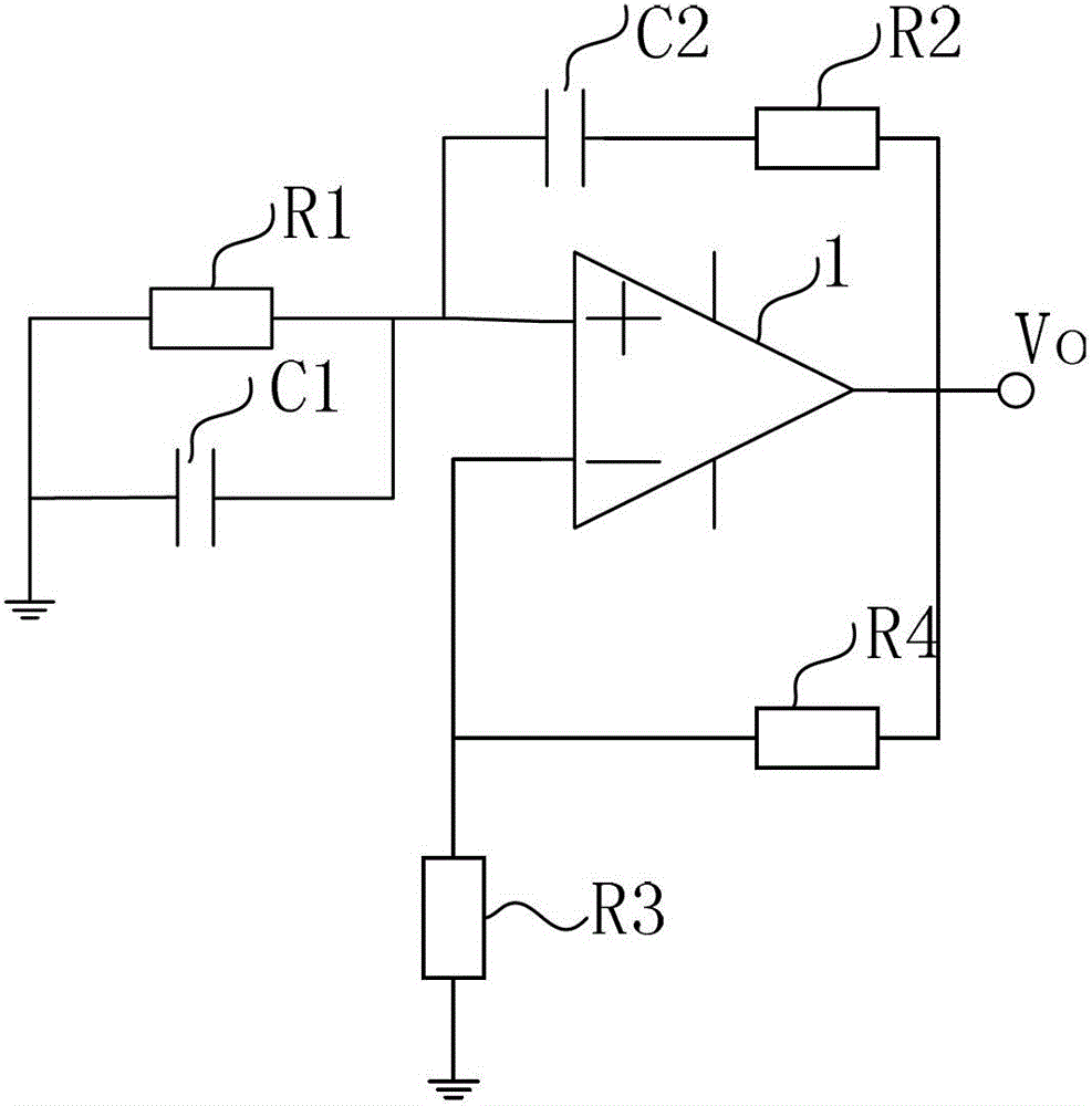
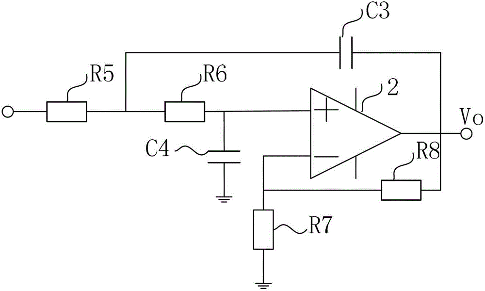
[0037] Such as figure 1 As shown, this embodiment provides a filter driving circuit for a frequency-sweeping light source, including a signal generation circuit, a filter circuit, a gain adjustment circuit and a filter load;

[0038] The signal generating circuit is used to generate a sine wave signal, the amplitude of the sine wave signal is consistent, and the frequency is adjustable;

[0039] The input end of the filter circuit is connected to the output end of the signal generation circuit, the filter circuit is used to filter out the noise outside the frequency band of the sine wave signal, and output the mixed waveform of the sine wave signal and narrowband noise;

[0040] The input end of the gain adjustment circuit is connected to the output end of the filter circuit, and the output end of the gain adjustment circuit is connected to the filter load; the gain adjustment circuit is used to perform a mixed waveform of the sine wave signal and narrowband noise Amplify, ou...

Embodiment 2

[0052] The filter driving circuit of a frequency-sweeping light source provided in this embodiment is the same as the technical solution described in Embodiment 1, as Figure 7 As shown, only the output end of the gain adjustment circuit is further connected with a drive enhancement circuit comprising an amplifier, and the output end of the drive enhancement circuit is connected to a filter load; the drive enhancement circuit is used to reduce the impedance of the sine wave amplified signal , enhance the driving ability.

[0053] Through the drive circuit described in Embodiment 1, the signal waveform meeting the requirements has been obtained, but the amplifier output of the gain adjustment circuit often has a large output resistance and insufficient drive capability. To drive high-frequency capacitive loads, a special drive enhancement circuit is required, which has the characteristics of small output impedance, large gain-bandwidth product, and supports bipolar high-voltage...

Embodiment 3

[0058] In actual operation, there are strict requirements on the stability of the filter, and among many influencing factors, temperature plays an important role. Therefore, it is necessary to add a constant temperature module to ensure the consistency of the temperature. A filter driving circuit for a frequency-sweeping light source provided in this embodiment, on the basis of the above embodiments, as Figure 11 As shown, the output end of the drive enhancement circuit is further connected with a constant temperature module, and the filter load is placed in the constant temperature box of the constant temperature module; the constant temperature module controls the filter by collecting the actual temperature of the filter load. The temperature of the load is regulated to ensure that the filter temperature is stable.

[0059] The constant temperature module includes a controlled power supply, a temperature setting circuit, a temperature sensor, a temperature controller, a te...


PUM


Abstract

The invention provides a filter drive circuit of a swept source. The filter drive circuit of the swept source comprises a signal generating circuit, a filter circuit, a gain adjusting circuit and a filter load, wherein the signal generating circuit is used for generating sine wave signals, an input end of the filter circuit is connected with an output end of the signal generating circuit, the filter circuit is used for filtering noise beyond a sine wave signal band, an input end of the gain adjusting circuit is connected with an output end of the filter circuit, an output end of the gain adjusting circuit is connected with the filter load, and the gain adjusting circuit is used for amplifying the mixed wave form of the sine wave signals and narrow band noise. According to the filter drive circuit of the swept source, output frequency of the swept source can be continuously adjustable between 20 KHz and 200 KHz, peak-to-peak value voltage can be 3 V, phase is adjustable, and output load is about 1 omega. Filter load stability is guaranteed, the requirements on modulation amplitude of different laser devices are met, and sweep frequency laser wavelength can be coordinated.

Description

technical field [0001] The invention relates to the fields of frequency-sweeping optical coherence tomography and optical fiber sensing, in particular to a filter driving circuit for a frequency-sweeping light source. Background technique [0002] The frequency-sweeping light source is a light source that outputs monochromatic waves of different wavelengths in the time domain. It only resolves monochromatic waves of a certain fixed wavelength from the broadband spectrum at a certain moment through the rapid scanning of narrow-band wavelength filters. In order to achieve fast, narrow instantaneous linewidth and linear broadband sweep output, it can be widely used in optical coherence tomography (Optical Coherence Tomography, OCT for short) and optical fiber sensing and other fields. Among them, as a key component of the frequency-sweeping light source, the drive of the filter is crucial to the parameters of the frequency-sweeping light source. [0003] One of the ways to rea...

Claims


Application Information

Patent Timeline
IPC IPC(8): H01S3/10H01S5/06
Inventor 王挺蒲忠杰董飒英赵士勇王荣军高洪燕
Owner LEPU MEDICAL TECH (BEIJING) CO LTD
Learn More