A method for processing small holes in carbon fiber composite materials by ring pulse laser

A pulsed laser, composite material technology, applied in laser welding equipment, metal processing equipment, manufacturing tools, etc., can solve the problems of non-penetration, thermal influence, tool wear, etc., to achieve the effect of increasing the aperture range and avoiding burrs

Active Publication Date: 2016-01-27
JIANGSU UNIV
View PDF8 Cites 3 Cited by
  • Summary
  • Abstract
  • Description
  • Claims
  • Application Information

AI Technical Summary

Problems solved by technology

[0007] The purpose of the present invention is to overcome defects such as delamination, tearing, and burrs that are easy to occur when drilling small holes in carbon fiber composite materials, and the cutter is easy to be severely worn; Long or too short lead to excessive melting or non-penetration of the plate, and there are serious thermal effects in the drilling of purely using laser thermal effect to melt and vaporize the material. A method for processing small holes on carbon fiber composite materials with ring pulse laser is provided.

Method used


Image

  • A method for processing small holes in carbon fiber composite materials by ring pulse laser
  • A method for processing small holes in carbon fiber composite materials by ring pulse laser

Examples


Embodiment 1

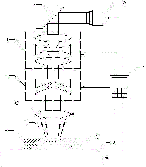
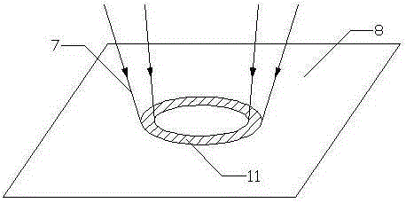
[0018] The carbon fiber volume fraction in the carbon fiber composite material is 50%: the backing plate 9 is fixed on the CNC workbench 10, the carbon fiber composite material 8 is fixed on the upper end surface of the backing plate 9, and the center of the ring pulse laser 7 is controlled by moving the control CNC workbench 10, The hole center of the carbon fiber composite material 8 and the hole center of the backing plate 9 are on the same axis, and the size of the hole on the backing plate 9 is 12 mm; the laser 2 is turned on, and the pulsed laser passes through the reflector 3, the optical shaping system 4, the ring beam generation system 5, After the focusing lens 6 acts on the surface of the composite material, the computer control system 1 adjusts the pulse width, energy, frequency and other parameters of the ring pulse laser 7 according to the characteristics of the carbon fiber composite material 8. The pulse width is 20ns, the energy is 5J, and the frequency is 5Hz. ...

Embodiment 2

[0020] The carbon fiber volume fraction in the carbon fiber composite material is 60%: the backing plate 9 is fixed on the CNC workbench 10, the carbon fiber composite material 8 is fixed on the upper end surface of the backing plate 9, and the center of the ring pulse laser 7 is controlled by moving the control CNC workbench 10, The hole center of the carbon fiber composite material 8 and the hole center of the backing plate 9 are on the same axis, and the size of the hole on the backing plate 9 is 12 mm; the laser 2 is turned on, and the pulsed laser passes through the reflector 3, the optical shaping system 4, the ring beam generation system 5, After the focusing lens 6 acts on the surface of the composite material, the computer control system 1 adjusts the pulse width, energy, frequency and other parameters of the ring pulse laser 7 according to the characteristics of the carbon fiber composite material 8. The pulse width is 10 ns, the energy is 10 J, and the frequency is 5 ...


PUM


Abstract

The invention relates to a laser drilling technology, in particular to a method for machining a small hole in a carbon fiber composite material by annular pulse laser. A plate is irradiated by using the annular pulse laser; the annular laser cuts into a material layer by layer under mutual combination of heat effect of irradiation of the annular pulse laser and force effect of shock wave; and finally, the carbon fiber composite material at an entire irradiation region is cut through to finish machining of the small hole. According to the characteristics of the carbon fiber composite material, the pulse width, the energy, the frequency and the light spot size of the annular pulse laser are adjusted. The phenomenon that burrs, tearing and layering are produced during machining of the carbon fiber composite material is effectively avoided, the thermal effect is reduced, and the machining quality of the small hole of the carbon fiber composite material is guaranteed.

Description

technical field [0001] The invention relates to laser drilling technology, in particular to a method for processing small holes on carbon fiber composite materials by using ring pulse laser, which is used for small hole processing of carbon fiber composite sheet materials. Background technique [0002] Carbon fiber composite material is a special material mixed with a soft and viscous matrix material and a high-strength, high-hardness fiber-reinforced material. It has the advantages of small specific gravity, good rigidity and high strength. As an advanced composite material, it has been used It has been widely used in aircraft structure. [0003] With the continuous expansion of the amount of carbon fiber composite materials, more and more machining work is required. However, its mechanical properties are anisotropic and the interlayer strength is low. During the drilling process, it is easy to cause delamination, Defects such as tears and burrs are especially serious at t...

Claims


Application Information

Patent Timeline
Patent Type & Authority Patents(China)
IPC IPC(8): B23K26/382B23K26/402B23K26/064B23K26/0622
Inventor 姜银方金华丁报程志军王春辉黄宇黄利伟
Owner JIANGSU UNIV
Why Eureka
Try Eureka