
Low-energy-consumption processing device for self-circulation sewage

A sewage treatment device and technology for treatment devices, which are applied in the fields of water/sewage multi-stage treatment, water/sludge/sewage treatment, chemical instruments and methods, etc. Day and night, seasonal changes, unstable technical operation, etc., to achieve the effect of strong resistance to hydraulic load shocks, low infrastructure operating costs, and low infrastructure and operating costs

Active Publication Date: 2013-05-01
王洪臣
View PDF10 Cites 3 Cited by
  • Summary
  • Abstract
  • Description
  • Claims
  • Application Information

AI Technical Summary

Problems solved by technology

In the morning, noon, and evening, the water consumption is relatively concentrated and the water volume is large, while the water volume in the early morning is basically zero; the population is small, and the water consumption standard is low; Generally, there is a peak discharge time, and it is difficult to correctly assess the pollution load of domestic sewage and its diurnal and seasonal changes; the concentration of various pollutants in sewage is low; there is a serious lack of maintenance management technicians and operation management experience
[0005] In view of the above characteristics, the shortcomings of the existing technology are as follows: due to the small amount of sewage water and the small design scale, the project construction cost and operating cost are too high; due to the large fluctuation of the water volume in a day, low flow or even zero flow occurs at night Due to the low pollutant load, the treatment efficiency is low when using the existing technology; due to the complexity of the existing process technology, professional technology is required It is difficult to realize the operation and maintenance management in remote rural areas

Method used


Image

  • Low-energy-consumption processing device for self-circulation sewage
  • Low-energy-consumption processing device for self-circulation sewage
  • Low-energy-consumption processing device for self-circulation sewage

Examples


Embodiment Construction

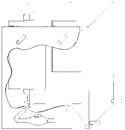
[0035] Such as figure 1 As shown, the sewage treatment device according to the present invention adopts the biofilter method of aerobic attachment, so that microorganisms aerobically attach to the surface of the filter material to form a biofilm, and absorb and degrade organic matter to achieve the purpose of purification. Different from other biological contact oxidation methods, the method of the present invention is to mix and dilute the influent and filtrate, and the treated sewage is continuously circulated and filtered inside the device, and is in constant contact with the biofilm, so as to achieve the purpose of purification. The process is very simple without the need for personnel to supervise. It is a fully automatic sewage treatment system, and the only power is the submersible pump located in the water inlet tank.

[0036] figure 2 The main components and flow of the present invention are shown. Main process: The sewage to be treated enters the water inlet tank ...


PUM


Abstract

The invention discloses a low-energy-consumption processing device for self-circulation sewage. The processing device comprises a water inlet tank, a regulating tank and a sand filter. The sand filter is connected in parallel between the water inlet tank and the regulating tank, the water inlet tank is connected with the sand filter through a reflux pump, and a check valve only allowing water to enter the water inlet tank from the regulating tank is arranged between the water inlet tank and the regulating tank; a water distributor for distributing sewage evenly to a sand filter surface layer is arranged at the top of the sand filter; a water collector for collecting water after sand filtration is arranged at the bottom of the sand filter; the height of the sand filter is higher than that of the regulating tank; the water level of the regulating tank is higher than that of the water inlet tank; and a water overflow weir for controlling the water to rise is arranged on the regulating tank. The processing device is economical, simple and convenient, efficient and suitable for processing rural domestic sewage rural.

Description

technical field [0001] The invention relates to a low energy consumption self-circulating sewage treatment device, in particular to a rural domestic sewage treatment device. Background technique [0002] According to the survey report, 96% of the villages have no drainage channels and sewage treatment systems, and the production and domestic sewage are discharged randomly, causing serious pollution to the rural environment, becoming a potential safety hazard in rural water sources, and exacerbating the crisis of fresh water resources. Improper domestic sewage has become one of the main reasons for the deterioration of water quality in rivers and lakes. [0003] At present, domestic sewage treatment devices include biological aerated filter (BAF) and membrane bioreactor (MBR) and so on. How to choose the treatment technology of domestic sewage in villages and towns, the key issue is to adapt to the actual situation of the villages and towns at present, in addition to meeting...

Claims


Application Information

Patent Timeline
IPC IPC(8): C02F9/14
Inventor 王洪臣罗涛梁帆齐鲁
Owner 王洪臣
Learn More